ENGLISH
ENGLISH
DEUTSCH
ESPAÑOL
FRANÇAIS
ITALIANO
NEDERLANDS
POLSKI
SVENSKA
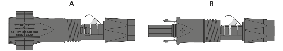
Overview of DC connectors
Negative (A) and positive (B) DC connectors
DC connection
Assembling the DC Connectors
Table of Contents
toggle menu
Information on this Document
Validity
Target Group
Content and Structure of this Document
Levels of Warning Messages
Symbols in the Document
Typographies in the document
Designations in the Document
Additional Information
Safety
Intended Use
IMPORTANT SAFETY INSTRUCTIONS
Scope of Delivery
Product overview
Device function
System Overview
Sunny Tripower X 25 as System Manager
Sunny Tripower X 25 with Sunny Home Manager
Sunny Tripower X 25 with SMA Data Manager as System Manager
Product Description
Symbols on the Product
Interfaces and Functions
User Interface
Device Key (DEV KEY)
Diagnostic function
Digital inputs
Integrated Plant Control
Modbus
Multifunction relay (MFR)
Grid Management Services
RS485 interface
Fast stop function
SMA ArcFix
SMA Dynamic Power Control
SMA ShadeFix
SMA Smart Connected
SMA Speedwire
Surge arrester type 1+2 or type 2
Wi-Fi connection to SMA 360° app and SMA Energy app
Wi-Fi
LED Signals
Mounting
Requirements for Mounting
Requirements for the Mounting Location
Permitted and prohibited mounting positions
Dimensions for mounting
Recommended clearances for mounting
Mount the product.
Mount the DC terminal cover (optional)
Electrical Connection
Requirements for the electrical connection
Permitted grid configurations
Residual-current monitoring unit
Load-break switch and cable protection
Additional protective grounding
Equipotential Bonding
Overvoltage category
AC cable requirements
Network cable requirements
Requirements for the PV modules per input
DC cable requirements
Signal cable requirements
Overview of the Connection Area
View from Below
Interior View
Electrical connection procedure
Connecting the AC Cable
Connecting additional protective grounding
Connecting the Network Cables
Connection of a Ripple Control Receiver
Digital input DI 1-4
Pin assignment DI 1-4
Circuitry overview DI 1-4
Connecting the ripple control receiver to DI 1-4
Connection to the Multifunction Relay
Digital output (MFR)
Pin assignment MFR
Connect signal source to MFR
Connection to digital input DI 5-6
Digital input DI 5-6
Pin assignment DI 5-6
Circuitry overview DI 5
Circuitry overview DI 6
Connecting Signal Source to Digital Input DI 5-6
DC connection
Overview of DC connectors
Assembling the DC Connectors
Connecting the PV Array
Commissioning
Procedure for commissioning as a subordinate device
Procedure for commissioning as System Manager
Commissioning the Inverter
Operation
Establishing a Connection to the User Interface
Connection in the local network
Access addresses for the product in the local network
Ports for data communication in the local network
Establishing a Connection via Ethernet in the local network
Establishing a Connection via WLAN in the Local Network
Direct connection via Wi-Fi
Connection options for Wi-Fi direct connection
Access information for direct Wi-Fi connection
Establishing a direct Wi-Fi connection with WPS
Establishing direct Wi-Fi connection with Wi-Fi network search
WPS function
Connection options with WPS
Activating WPS for automatic connection
Activating WPS for direct connection to a smart device
Design of the User Interface
Access rights to the user interface
Changing parameters
Bookmarking Instantaneous Values
SMA ArcFix
Digital output (MFR)
Use of the digital output (MFR)
Configure the digital output (MFR)
Digital input
Configure the digital input DI 5 for the fast stop
Configuring the digital input DI 1-4 for the external setpoint
Control and Regulation of Grid Management Services via Digital Inputs
Use of the Inverter’s Digital Inputs Together with a Sunny Home Manager
Instantaneous Values for Verifying Active Power Limitation
Grid and PV system protection
Generating the I-V Characteristic Curve
Activating a Digital Product
Energy management
Activating the energy management
Deactivating the energy management
Predefined operating modes
Available operating modes
Add new operating mode
Setting options for peak load shaving
Create a new schedule
Export schedules
Import schedules
Backup file
Function and content of the backup file
Creating a Backup File
Carry out a manual firmware update
Device Administration
Register Devices
Delete devices
Restart the inverter via the user interface
Resetting the product to default setting
Delete user accounts
Configuring Service Access
Q on Demand 24/7
Country standard
Overview of Grid Types
Residential Optimization
Disconnecting the Inverter from Voltage Sources
Cleaning
Troubleshooting
Event messages
Event 101
Event 102
Event 103
Event 105
Event 301
Event 302
Event 401
Event 404
Event 501
Event 507
Event 601
Event 701
Event 1001
Event 1101
Event 1302
Event 1501
Event 3501
Event 3523
Event 3601
Event 3701
Event 3901
Event 3902
Event 4301
Event 6001-6499
Event 6101
Event 6107
Event 6202
Event 6401
Event 6404
Event 6405
Event 6406
Event 6407
Event 6422
Event 6438
Event 6501
Event 6511
Event 6512
Event 6602
Event 7001
Event 7014
Event 7015
Event 7702
Event 7703
Event 7801
Event 8501
Event 8708
Event 8709
Event 8710
Event 9002
Event 9003
Event 9007
Event 9035
Calculating the insulation resistance
Checking the PV System for Ground Faults
Cleaning the Fans
Manual restart after electric arc
Create Diagnostics Data
Decommissioning the Product
Disposal
Technical Data
General Data
DC Input
AC output
Digital inputs
Digital output (multifunction relay)
Communication
Data Storage Capacity
Efficiency
Protective Devices
Climatic Conditions
Equipment
Torques
Accessories
Contact
EU Declaration of Conformity