
Connecting the ripple control receiver to DI 1-4
 Qualified person
Connection of the ripple control receiver must be carried out at the inverter that is to be configured as System Manager.
Procedure:
- Connect the connection cable to the ripple control receiver or the remote terminal unit (see the manual from manufacturer).
- Disconnect the inverter from all voltage sources ( > Disconnecting the Inverter from Voltage Sources).
- Unscrew the swivel nut from the cable gland.
- Remove the four-hole cable support sleeve from the cable gland.
- Remove the plug from one of the enclosure openings and cut into the enclosure opening with a utility knife.
- Insert the cable into the enclosure opening.
- Press the four-hole cable support sleeve with the cable into the cable gland and guide the cable to slot DI 1-4. Ensure that the unused enclosure openings of the four-hole cable support sleeve are sealed with sealing plugs.
- Strip 6 mm of the cable insulation at maximum.
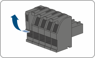
- Release the conductor entries on the supplied 5-pole connector.
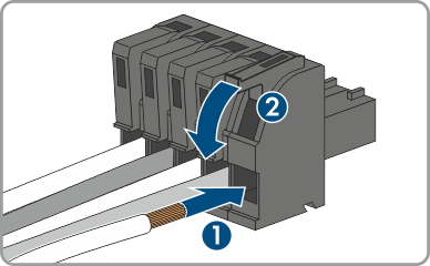
- Connect the conductors of the connection cable to the supplied 5-pole connector. To do so, plug the conductors into the conductor entries and close the conductor entries. Observe the connector assignment.
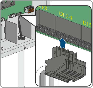
- Plug the 5-pole connector into the socket DI 1-4 on the product. Observe the pin assignment.
- Ensure that the connector is securely in place.
- Ensure that all conductors are correctly connected.
- Ensure that the conductors sit securely in the terminal points.
- Tighten the swivel nut on the cable gland hand-tight.
Also see: