
Connecting contact for fast stop
 Qualified person

Observe pin assignment for grid and PV system protection
Note that when connecting the grid and PV system protection required by VDE-AR-N-4105, the connection must be made to the pin with the FS1 assignment. The pin with the FS2 assignment is considered a universal connection and is unsuitable for implementing grid and PV system protection. It is used for the connection of an external switch, for example.
Procedure:
- Connect the connection cable to the ripple control receiver or the remote terminal unit (see the manual from manufacturer).
- Disconnect the inverter from voltage sources and secure it against being switched on again ( > Disconnecting the Inverter from Voltage Sources).
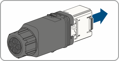
- Remove the connector with cable gland.
- Pull the communication assembly out of the cable gland.
- Unscrew the swivel nut from the cable gland.
- Thread the swivel nut over the cable.
- Remove the four-hole cable support sleeve from the cable gland.
- Remove the plug from one of the enclosure openings and cut into the enclosure opening with a utility knife.
- Insert the cable into the enclosure opening.
- Strip off a maximum of 6 mm of the cable insulation.
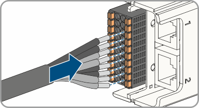
- Connect the conductors of the connection cable to the digital inputs of the fast stop. To do so, plug the conductors into the conductor entries and close the conductor entries. Observe the connector assignment.
- Ensure that all conductors are correctly connected.
- Ensure that the conductors sit securely in the terminal points.
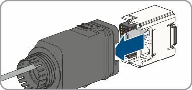
- Plug the communication assembly onto the cable gland.
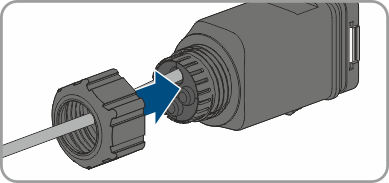
- Fasten the union nut on the cable gland and screw hand-tight.
- Plug the communication assembly with the cable gland into the terminal on the inverter.
Also see: