
Connecting the Network Cables
 Qualified person
 DANGER
Danger to life due to electric shock in case of overvoltages and if surge protection is missing
Overvoltages (e.g., in the event of a flash of lightning) can be further conducted into the building and to other connected devices in the same network via the network cables or other data cables if there is no surge protection. Touching live parts and cables results in death or lethal injuries due to electric shock.
- Ensure that all devices in the same network are integrated in the existing overvoltage protection.
- When laying the network cable outdoors, ensure that there is suitable surge protection at the network cable transition from the product outdoors to the network inside the building.
Additionally required material (not included in the scope of delivery):
Network cable
Where required: Field-assembly RJ45 connector.
Procedure:
- Disconnect the inverter from voltage sources and secure it against being switched on again ( > Disconnecting the Inverter from Voltage Sources).
- When using a self-assembly network cable, assemble the RJ45 connectors and connect them to the network cable (see connector documentation).
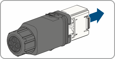
- Remove the communication assembly with the cable gland from the scope of delivery.
- Pull the communication assembly out of the cable gland.
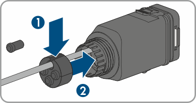
- Unscrew the swivel nut from the cable gland.
- Remove the four-hole cable support sleeve from the cable gland and remove one of the plugs from the enclosure openings and cut into each enclosure opening with a utility knife.
- Thread the network cable through the union nut and the cover of the communication connection.
- When using a self-assembly network cable, assemble the RJ45 connectors and connect them to each network cable (see connector documentation).
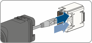
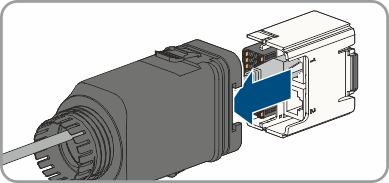
- Put the RJ45 plug of the cable into one of the network jacks of the communication assembly.
- Tug lightly to ensure that the network cable is secure.
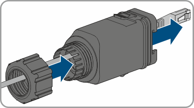
- Plug the communication assembly onto the cable gland.
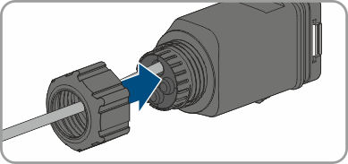
- Press the four-hole cable support sleeve into the cable gland.
- Fasten the union nut on the cable gland and screw hand-tight.
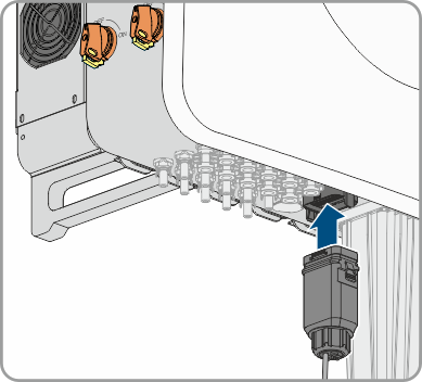
- Plug the communication assembly with the cable gland into the terminal on the inverter.
- If the inverter is installed outdoors, install overvoltage protection for all components in the network.
- To integrate the inverter into a local network, connect the other end of the network cable to the local network (e.g., via a router).
Also see: