
Connecting the Inverter to the Utility Grid
 Qualified person
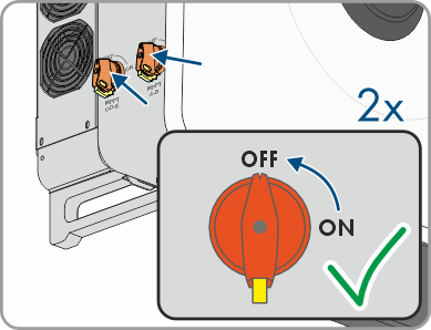
- Disconnect the miniature circuit breaker from all 3 line conductors and secure against reconnection.
- Make sure that all DC load-break switches have been switched off and secured against reconnection.
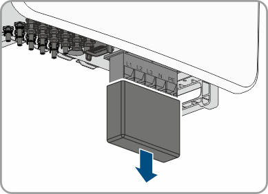
- Remove the cover from the AC connection area.
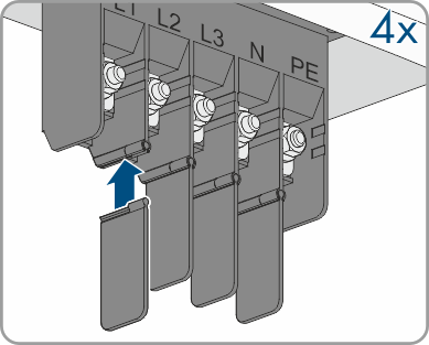
- Retrieve the 4 cable touch guards of the conductors from the scope of delivery and push them into the recess in the connection area.
- Remove the cover of the AC connection area from the scope of delivery of the inverter.
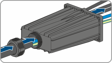
- Thread the AC cable through the cable gland into the AC Connection Unit. If necessary, slightly loosen the swivel nut of the cable gland. In case of AC cables that require a clamping area < 35 mm, replace the seal insert of the cable gland by the seal insert with reduced clamping range.
- Dismantle the AC cable.
- Strip off the insulation of L1, L2, L3, N and PE by 30 mm.
- For conductors made of aluminum, remove the oxide film and apply protective grease to the conductors.
- Pull 1 heat-shrink tubing each over conductor L1, L2, L3, N and PE (grounding conductor) and crimp the ring terminal lug ( > Crimping of Ring Terminal Lug).
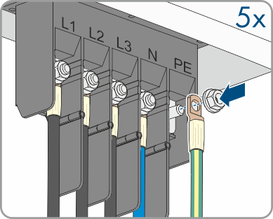
- Place the conductors with the ring terminal lugs (max. Ø=26 mm) according to the labeling for L1, L2, L3, N and PE onto the stud bolts (M10, tightening torque: 12 Nm) in the upper area, each with 1 washer and hex nut, and tighten them using a ratchet.
- Ensure that the correct conductors are assigned to all the terminals.
- Ensure that all conductors are securely in place.
- Ensure that the AC cable is not under tension.
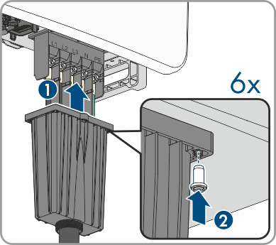
- Attach the AC-Connection Unit of the AC connection area using the 6 screws (M4x8, tightening torque: 1.6 Nm) to the enclosure of the inverter.
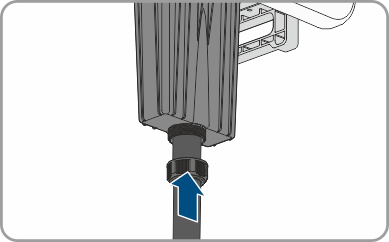
- Tighten the swivel nut on the cable gland hand-tight.
Also see: