
Connecting the Digital Input
 Qualified person
- Connect the connection cable to the ripple control receiver or the remote terminal unit (see the manual from manufacturer).
- Disconnect the inverter from voltage sources and secure it against being switched on again ( > Disconnecting the Inverter from Voltage Sources).
- Remove the connector with cable gland.
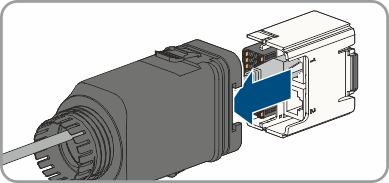
- Pull the communication assembly out of the cable gland.
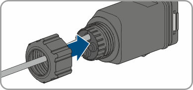
- Unscrew the swivel nut from the cable gland.
- Thread the swivel nut over the cable.
- Remove the four-hole cable support sleeve from the cable gland.
- Remove the plug from one of the enclosure openings and cut into the enclosure opening with a utility knife.
- Insert the cable into the enclosure opening.
- Strip off a maximum of 6 mm of the cable insulation.
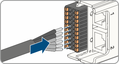
- Connect the conductors of the connection cable to the digital inputs DI: D1-D4, Vcc. To do so, plug the conductors into the conductor entries and close the conductor entries. Observe the connector assignment.
- Ensure that all conductors are correctly connected.
- Ensure that the conductors sit securely in the terminal points.
- Plug the communication assembly onto the cable gland.
- Fasten the union nut on the cable gland and screw hand-tight.
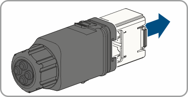
- Plug the communication assembly with the cable gland into the terminal on the inverter.
Also see: