ENGLISH
ENGLISH
DEUTSCH
ESPAÑOL
FRANÇAIS
ITALIANO
NEDERLANDS
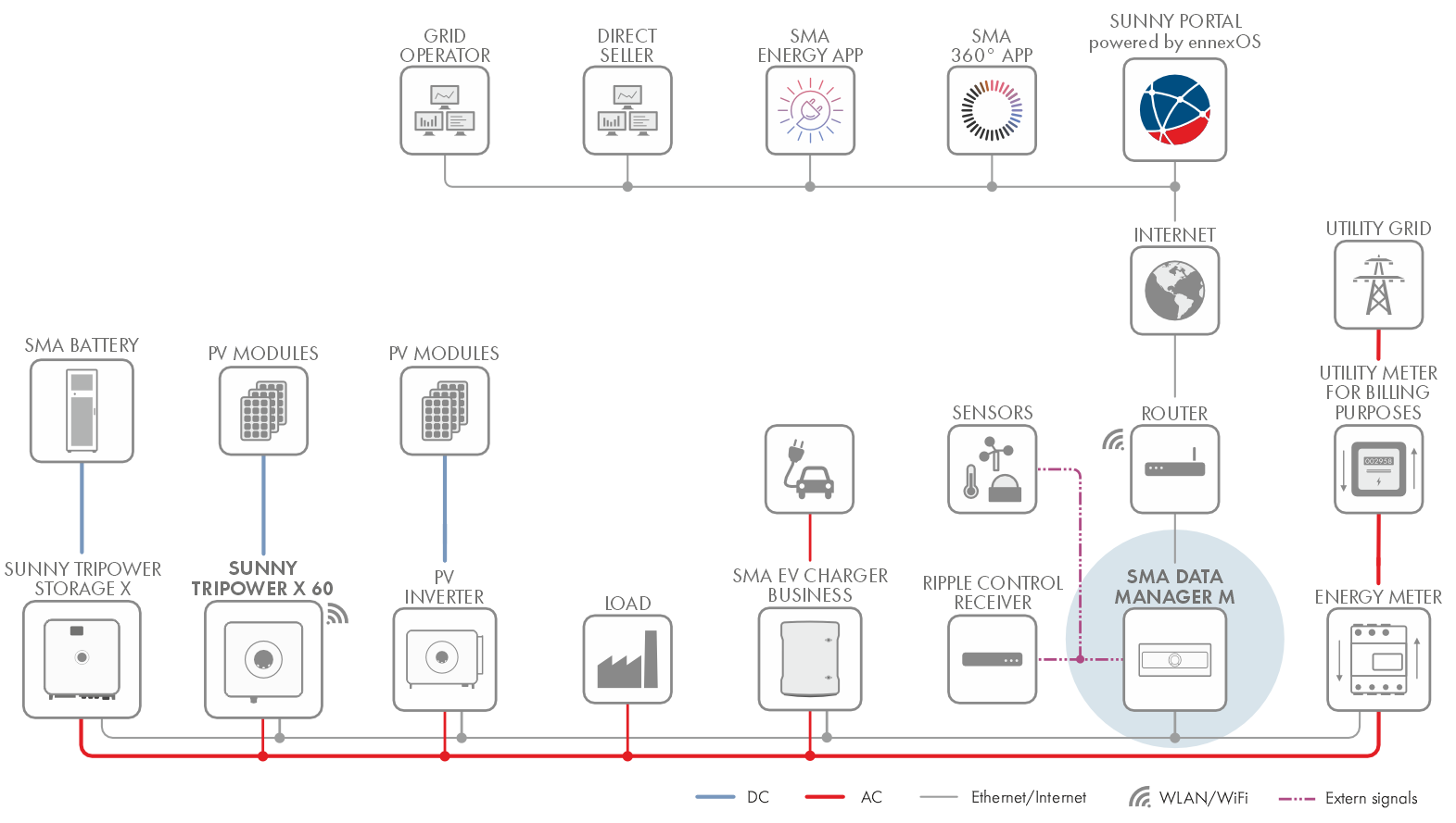
Sunny Tripower with SMA Data Manager as System Manager
System with Sunny Tripower X and SMA Data Manager as system manager
Sunny Tripower as System Manager
Interfaces and Functions
Table of Contents
toggle menu
Information on this Document
Validity
Target Group
Content and Structure of this Document
Levels of Warning Messages
Symbols in the Document
Typographies in the document
Designations in the Document
Additional Information
Safety
Intended Use
IMPORTANT SAFETY INFORMATION
Scope of Delivery
Product overview
Device function
Product Description
Symbols on the Product
System overview
Sunny Tripower as System Manager
Sunny Tripower with SMA Data Manager as System Manager
Interfaces and Functions
User Interface
Device Key (DEV KEY)
Digital inputs
Modbus
Grid Management Services
Fast stop function
SMA ArcFix
SMA Dynamic Power Control
SMA Dynamic Power Control
SMA ShadeFix
SMA Smart Connected
SMA Speedwire
Wi-Fi connection to SMA 360° app and SMA Energy app
Wi-Fi connection to SMA 360° app and SMA Energy app
LED Signals
Mounting
Requirements for Mounting
Requirements for the Mounting Location
Permitted and prohibited mounting positions
Dimensions for Mounting
Recommended clearances for mounting
Mounting the Inverter
Electrical Connection
Requirements for the electrical connection
Equipotential Bonding
Load-break switch and cable protection
Network cable requirements
AC cable requirements
DC cable requirements
Signal cable requirements
Overview of the Connection Area
View from Below
Overview of the COM assembly connections
Electrical connection procedure
Connecting the Inverter to the Utility Grid
Crimping of Ring Terminal Lug
Connecting the external protective grounding
Connecting the Network Cables
Connection for Active Power Limitation
Procedure for Connecting the Active Power Limitation
Digital input DI: D1-D4, Vcc
Pin assignment DI: D1-D4, Vcc
Circuitry overview DI: D1-D4, Vcc
Connecting the Digital Input
Connection for Digital Fast-Stop Inputs
Procedure for Connecting to the Fast-Stop Input
Pin assignment for fast stop
Fast stop circuitry overview
Circuitry Overview of Grid and Pv System Protection
Connecting contact for fast stop
Connection to the Multifunction Relay
Procedure for Connecting the Multifunction Relay
Digital output (MFR)
Pin assignment for multifunction relay
Circuitry Overview
Connecting the Multifunction Relay
DC connection
Overview of DC connectors
Assembling the DC Connectors
Connecting the PV Array
Commissioning
Procedure for commissioning as a subordinate device
Procedure for commissioning as System Manager
Switching the Inverter On
Operation
Use of the user interface powered by ennexOS
Disconnecting the Inverter from Voltage Sources
Troubleshooting
Event messages
Event 102
Event 301
Event 401
Event 501
Event 601
Event 701
Event 901
Event 1302
Event 1401
Event 3401
Event 3402
Event 3407
Event 3410
Event 3411
Event 3501
Event 3601
Event 3701
Event 3801
Event 3804
Event 4001
Event 4301
Event 6001-6499
Event 6155
Event 6202
Event 6405
Event 6438
Event 6501
Event 6603
Event 6604
Event 6606
Event 7015
Event 7702
Event 7703
Calculating the insulation resistance
Decommissioning
Disconnecting the Terminals from the Inverter
Disassembling the DC Connectors
Disassembling the Inverter
Disposal
Technical Data
General Data
DC Input
AC output
Data Storage Capacity
Communication
Climatic Conditions
Efficiency
Protective devices
Equipment
EU Declaration of Conformity
Contact