
Connecting the Network Cables
 Qualified person
 DANGER
Danger to life due to electric shock in case of overvoltages and if surge protection is missing
Overvoltages (e. g. in the event of a flash of lightning) can be further conducted into the building and to other connected devices in the same network via the network cables or other data cables if there is no surge protection. Touching live parts and cables results in death or lethal injuries due to electric shock.
- Ensure that all devices in the same network and the battery are integrated into the existing surge protection.
- When laying the network cables or other data cables outdoors, it must be ensured that a suitable surge protection device is provided at the transition point of the cable from the product or the battery outdoors to the inside of a building.
Additionally required material (not included in the scope of delivery):
Network cables
Where required: Field-assembly RJ45 connector with metal enclosure
Procedure:
- Disconnect the product from voltage sources ( > Disconnecting the Inverter from Voltage Sources).
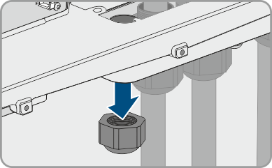
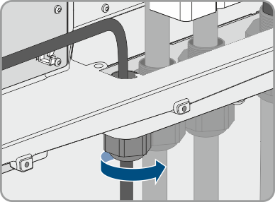
- Unscrew the swivel nut from the cable gland.
- Thread a swivel nut over each network cable.
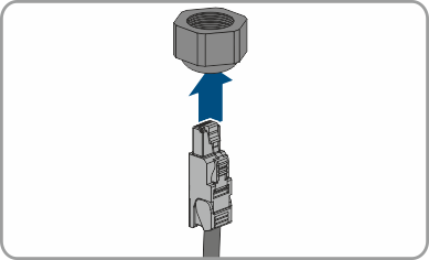
- Remove the two-hole cable support sleeve from the cable gland.
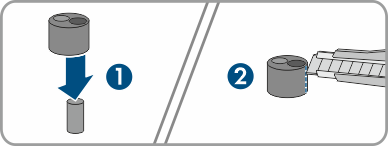
- For each network cable, remove one of the plugs from the enclosure openings and for each network cable cut an enclosure opening with a utility knife.
- Insert each network cable into a 2-hole cable support sleeve.
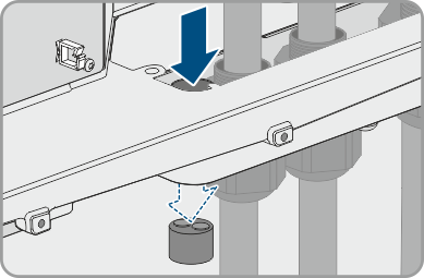
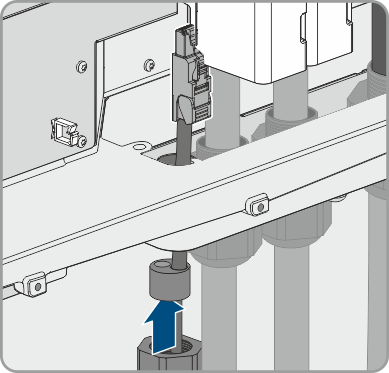
- Press the 2-hole cable support sleeve into the cable gland and guide each network cable to the network port. Lay each cable according to the installation plan and attach it to the brackets.
- When using self-assembly cables, assemble the RJ45 connectors and connect them to the cable (refer to the documentation of the connector).
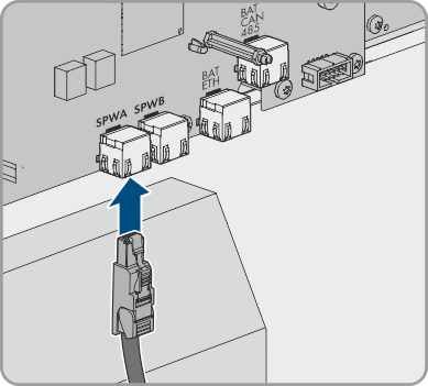
- Plug the RJ45 connector of the network cable into the socket SPWA or SPWB of the communication assembly.
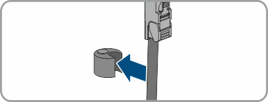
- Attach one ferrite included in the scope of delivery to each network cable.
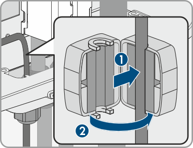
- Firmly tighten the swivel nut on each cable gland.
- Ensure that the network cables are securely in place by pulling slightly on each of them.
- Tighten the swivel nut on the cable gland hand-tight. This will secure the network cables in place.
- If the product is installed outdoors, install overvoltage protection for all components in the network.
- Either connect the other end of the network cable directly to the local network (e.g., via a router) or connect all present converters in the system to each other in line topology and connect the first or last converter in the line to the local network.
Also see: