
Requirements for Mounting
Requirements for the mounting location:
 WARNING
Danger to life due to fire or explosion
Despite careful construction, electrical devices can cause fires. This can result in death or serious injury.
- Do not mount the product in areas containing highly flammable materials or gases.
- Do not mount the product in potentially explosive atmospheres.
-
The mounting location must be inaccessible to children.
The installation site must be suitable for the weight and dimensions of the product ( > Technical Data).
-
The installation site can be exposed to direct solar irradiation. There is, however, the possibility that the product reduces its power output to avoid overheating due to high temperatures.
The installation site should be freely and safely accessible at all times without the need for any auxiliary equipment (such as scaffolding or lifting platforms). Non-fulfillment of these criteria may restrict servicing.
-
The DC load-break switch of the product must always be freely accessible.
All ambient conditions must be met ( > Technical Data).
Permitted and prohibited mounting positions:
The product may only be mounted in a permitted position. This will ensure that no moisture can penetrate the product.
The product should be mounted such that the LED signals can be read off without difficulty.

Permitted and prohibited mounting positions
Dimensions for mounting:
NOTICE
Damage to the enclosure by using excessively long screws for attaching profile rails
The maximum thread depth of the drill holes for fastening feet and profile rails is 17 mm. If screws are used with a length that exceeds the thread depth, the drill holes fracture and the enclosure will be damaged.
- When selecting the screws for fastening the profile rails, observe the thread depth of 14 mm to 17 mm and ensure that the thread depth is not exceeded.
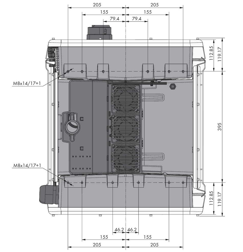
Position of the anchoring points(Dimensions in mm)
Structural Stability:
When mounting with feet or profile rails, the width of one foot or the profile rail must be at least 175 mm to ensure structural stability.
The inverter must be attached under the following conditions:
Inclination of the support surface: < 3°
Wind speed (without wind gusts): < 25 m/s
Height of the feet or the profile rail: > 100 mm
When mounting with profile rails, an attachment or fixation by loading is required. When mounting with profile rails, SMA Solar Technology AG recommends to bolt the profile rails e.g. to the profile of the module frame or to attach a sheet metal (which can be weighted with stones or with sandbags) at the profile rails. This will ensure that the inverter is fixed.
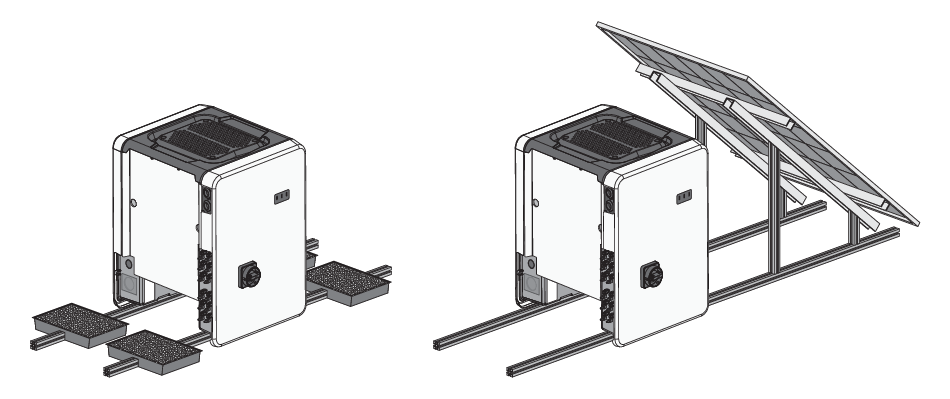
Attachment of the inverters (examples)
Recommended clearances:
If you maintain the recommended clearances, adequate heat dissipation will be ensured. Thus, you will prevent power reduction due to excessive temperature.
-
Maintain the recommended clearances to roof edges, skylights, walls as well as to other inverters or objects. This ensures that the DC load-break switch on the inverter can be operated easily and the LED signals can be read without difficulty.
-
For possible service deployments, SMA Solar Technology AG recommends ensuring sufficient clearance from walls, other inverters or objects on all four sides of the inverter enclosure. Non-fulfillment of these criteria may restrict servicing.
If multiple products are mounted in areas with high ambient temperatures, increase the clearances between the products and ensure sufficient fresh-air supply.

Recommended clearances when using the universal assembly system (UMS_KIT-10)
When using the universal assembly system (UMS_KIT-10), it is possible to deviate from the recommended clearances.
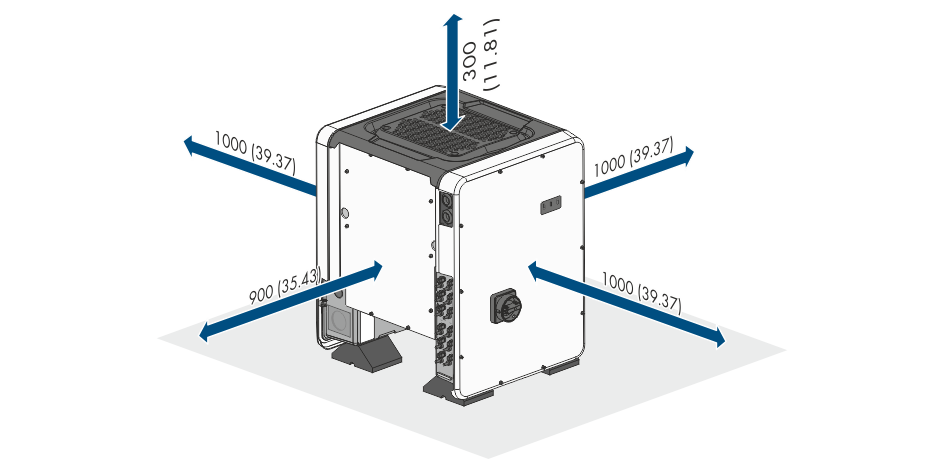
Recommended clearances(Dimensions in mm)