
Disconnecting the Inverter from Voltage Sources
 Qualified person
Prior to performing any work on the product, always disconnect it from all voltage sources as described in this section. Always adhere to the prescribed sequence.
WARNING
Danger to life due to electric shock from destruction of the measuring device due to overvoltage
Overvoltage can damage a measuring device and result in voltage being present in the enclosure of the measuring device. Touching the live enclosure of the measuring device results in death or lethal injuries due to electric shock.
- Only use measuring devices with a DC input voltage range of 1000 V or higher.
Procedure:
- Disconnect the AC miniature circuit breaker and secure against reconnection.
- Turn the DC load-break switch of the inverter to position O.
- If your country requires the DC load-break switch to be protected against reconnection, secure the DC load-break switch against reconnection with a suitable padlock.
- If the multifunction relay is used, switch off any supply voltage to the load.
- Wait until the LEDs have gone out.
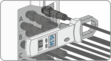
- Use a current clamp to ensure that no current is present in the DC cables.
- Note the position of the DC connectors.
- Wear insulated gloves and use insulated tools when working on the DC connectors.
- Ensure that the DC connectors are in perfect condition and that none of the DC conductors or DC plug contacts are exposed.
- Carefully release and remove the DC connectors as described in the following.
- Release and remove the DC connectors. To do so, insert a flat-blade screwdriver or an angled screwdriver (blade width: 3.5 mm) into one of the side slots and pull the DC connectors out. When doing so, do not lever the DC connectors out, but insert the tool into one of the side slots only to release the locking mechanism, and do not pull on the cable.
- Ensure that the DC connectors on the product and those that are equipped with DC conductors are in perfect condition and that none of the DC conductors or DC plug contacts are exposed.
- Ensure that no voltage is present at the DC inputs on the inverter using a suitable measuring device.
- Unscrew (TX25) all 10 screws of the enclosure lid of the AC-Connection Unit and remove the enclosure lid carefully towards the front.
- Set the screws and the enclosure lid aside and store safely.
- Ensure there is no voltage on the AC terminal block between L1 and N, L2 and N, and L3 and N using a suitable measuring device. To do so, insert the test probe (maximum diameter: 2.5 mm) into the measuring points of the respective terminal blocks.
- Ensure that there is no voltage on the AC terminal block between L1 and grounding conductor, L2 and grounding conductor, and L3 and grounding conductor using a suitable measuring device. To do so, insert the test probe (maximum diameter: 2.5 mm) into the measuring points of the respective terminal blocks.
 DANGER
Danger to life due to electric shock when touching exposed DC conductors or DC plug contacts if the DC connectors are damaged or loose
The DC connectors can break or become damaged, become free of the DC cables, or no longer be connected correctly if the DC connectors are released and disconnected incorrectly. This can result in the DC conductors or DC plug contacts being exposed. Touching live DC conductors or DC plug connectors will result in death or serious injury due to electric shock.


