
Requirements for the AC Connection
AC cable requirements as follows:
Conductor type: aluminum and copper wire
External diameter: 35 mm to 48 mm / 26 mm to 39 mm
Conductor cross-section of grounding conductor: 25 mm² to 120 mm²
-
Conductor cross-section of line conductor and neutral conductor: 35 mm² to 120 mm²
Insulation stripping length: 30 mm
Sheath stripping length: 290 mm
The cable must be dimensioned in accordance with the local and national directives for the dimensioning of cables. The requirements for the minimum wire size derive from these directives. Examples of factors influencing cable dimensioning are: nominal AC current, type of cable, routing method, cable bundling, ambient temperature and maximum desired line losses (for calculation of line losses, see the design software "Sunny Design" from software version 2.0 at www.SMA-Solar.com).
Overview of the required length of the conductor inside the AC connection unit

Interior view of the AC connection unit with dimensions for the conductors (Dimensions in mm)
Load-break switch and cable protection:
NOTICE
Damage to the inverter due to the use of screw-type fuses as load-break switches
Screw-type fuses (e.g. DIAZED fuse or NEOZED fuse) are not load-break switches.
- Do not use screw-type fuses as load-break switches.
- Use a load-break switch or circuit breaker as a load disconnection unit (for information and design examples, see the Technical Information at www.SMA-Solar.com).
In PV systems with multiple inverters, protect each inverter with a separate three-phase circuit breaker. Make sure to observe the maximum permissible fuse protection ( > Technical Data). This will prevent residual voltage from being present at the corresponding cable after disconnection.
-
Loads installed between the inverter and the circuit breaker must be fused separately.
Residual-current monitoring unit:
The inverter does not require an external residual-current device when operating. If local regulations require the use of a residual-current device, the following must be observed:
-
The inverter is compatible with type B residual-current devices that have a rated residual current of 300 mA or higher (information about the selection of a residual-current device see technical information "Criteria for Selecting a Residual-Current Device" at www.SMA-Solar.com). Each inverter in the system must be connected to the utility grid via a separate residual-current device.
-
When using residual-current devices with a rated residual current < 500 mA, the rated residual current must be set in the inverter ( > Setting the Rated Residual Current of the Residual-Current Device). In this way the inverter reduces the operational leakage currents and prevents a false triggering of the residual-current device.
Overvoltage category:
The product can be used in grids of overvoltage category III or lower in accordance with IEC 60664-1. That means that the product can be permanently connected to the grid-connection point of a building. In case of installations with long outdoor cabling routes, additional measures to reduce overvoltage category IV to overvoltage category III are required (see the Technical Information "Overvoltage Protection" at www.SMA-Solar.com).
Grid configurations and grounding
The following grid configurations are permitted for the connection of the inverter: TN-C, TN-S, TN-C-S, TT1). Operation in IT or DELTA IT grids is not permitted.
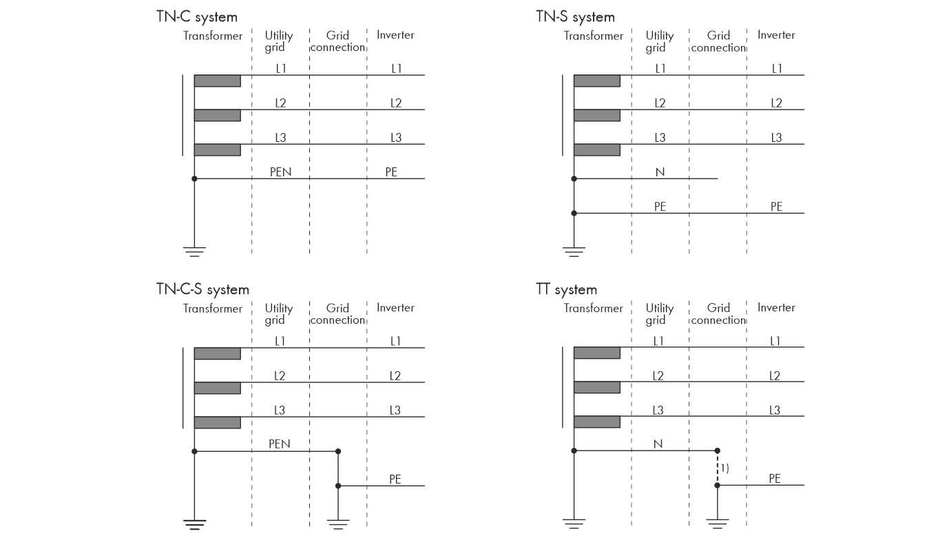
1) It must be ensured that the local grounding has a sufficiently low-impedance connection to the grounding of the transformer, otherwise operational leakage currents can lead to potential differences. For error-free operation, the ground potential at the neutral point of the transformer must be the same as that of the grounding conductor connection on the inverter. SMA Solar Technology AG recommends a bridge between N and grounding conductor at the point of interconnection to ensure error-free operation. Improper implementation of the transformer/grid connection with regard to low-impedance grounding/zeroing of the neutral point can lead to a device defect that is not covered by the warranty.