Connection to the Multifunction Relay
 Qualified person
Requirement:
The technical requirements of the multifunction relay must be met ( > Technical Data).
Cable requirements:
Conductor cross-section: 0.2 mm² to 1.5 mm²
The cable type and cable-laying method must be appropriate for the application and location.
Procedure:
- Disconnect the inverter from all voltage sources ( > Disconnecting the Inverter from Voltage Sources).
- If the enclosure lid of the DC-Connection Unit is closed, remove it as follows: Unscrew all ten screws with a Torx screwdriver (TX25) and remove the enclosure lid carefully forward.
- Set the screws and the enclosure lid aside and store safely.
- Remove the swivel nut from the cable gland for the communication cable.
- Remove the two-hole cable support sleeve from the cable gland and insert the cable into the enclosure opening of the two-hole cable support sleeve.
- Press the two-hole cable support sleeve with the cable into the cable gland and guide the cable to the communication assembly in the DC Connection Unit. Ensure that any unused enclosure openings of the two-hole cable support sleeve are sealed with sealing plugs.
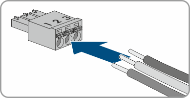
- Strip 9 mm of the cable insulation at maximum.
- Connect the cable to the 3-pole terminal block according to the circuit diagram, depending on the operating mode ( > Connection Options). Ensure that the conductors are plugged completely into the terminal points up to their insulation.
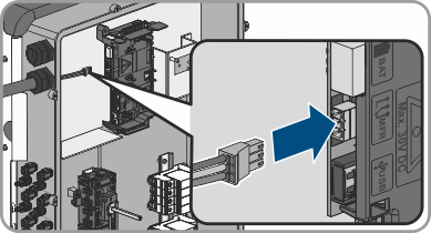
- Stick the 3-pole terminal block with the connected conductors into the MFR slot on the communication assembly in the inverter.
- Ensure that the terminal block is securely in place.
- Ensure that all conductors are correctly connected.
- Ensure that the conductors sit securely in the terminal points. Tip: To release the conductors, open the terminal points using a suitable tool.
- Tighten the swivel nut on the cable gland hand-tight.
 DANGER
Danger to life due to high voltages