
Connecting Signal Source to Digital Input
The digital signals can be transmitted to the DI jack. A buffer module, for example, can be used as a digital signal source.
Additionally required material (not included in the scope of delivery):
-
Digital signal source with up to 4 potential-free contacts
-
Connection cable
Signal cable requirements:
The cable length and quality affect the quality of the signal. Observe the following cable requirements:
-
Number of wires: at least 2
-
Conductor cross-section: 0.2 mm² to 1.5 mm² (32 AWG to 16 AWG)
-
Maximum cable length: 30 m (98 ft)
-
UV-resistant for outdoor use
Requirements:
The signal source must be technically suitable for connection to the digital inputs ( > Technical Data).
The connection cable must be prepared for connection to the multipole terminal block ( > Preparing the Connection Cable).
Overview:

Pin assignment for terminal DI/DO
Pin | Pin assignment | Explanation |
|---|---|---|
1 | DI1 | Condition of the buffer module |
2 | DI2 | Reserved for future applications |
3 | DI3 | Fast stop* |
4 | DI4 | Reserved for future applications |
5 | 24 V | Voltage supply output |
1 | DO1 | Reserved for future applications |
2 | DO2 | Reserved for future applications |
3 | DO3 | Reserved for future applications |
4 | DO4 | Reserved for future applications |
5 | GND | Ground |
* For information on SMA products with fast-stop function see manual of the SMA products.
Circuitry overview:
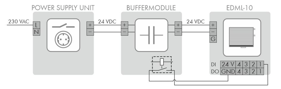
Connection of a buffer module (example)
Procedure:
- Connect the connection cable to the digital signal source (see the manual from manufacturer).
- Connect the connection cable to the supplied 5-pole terminal blocks. To do this, release the screws of the required terminal points using a suitable tool, plug the wires into the terminal points and tighten the screws of the terminal points hand-tight.
- Connect the 5-pole terminal blocks to terminal DI. Observe the pin assignment.
- Ensure that the wires are correctly connected and fit tightly.
- Note the terminal assignment.