
Overview of the Connection Area
Overview of the connection area
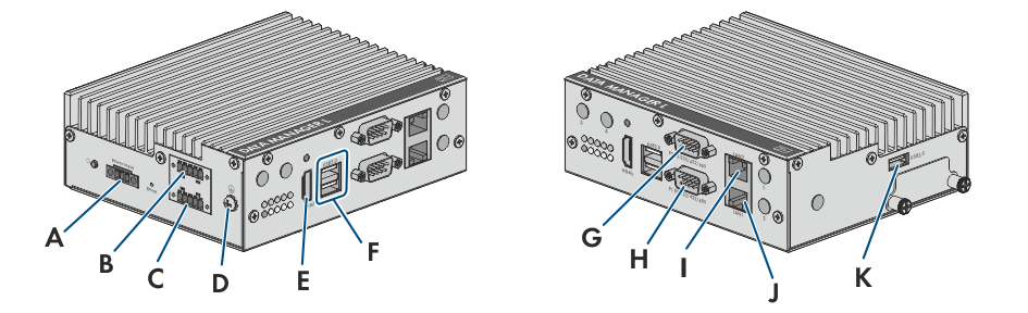
Position | Designation | Explanation |
|---|---|---|
A | Power Input | Jack for connecting the voltage supply |
B | DI | Jack for the connection of digital input signals |
C | DO | Jack for the connection of digital output signals |
D |
| Connection point for connecting the grounding conductor |
E | HDMI | Reserved for future applications |
F | USB2.0 | USB 2.0 ports for manual updates |
G | P2 RS-232/422/485 | Reserved for future applications |
H | P1 RS-232/422/485 | Reserved for future applications |
I | LAN2 | Network port with status LEDs for the connection to a network with external nodes |
J | LAN1 | Network port with status LEDs for the connection to a network with internal nodes |
K | USB3.0 | USB 3.0 port for manual updates |
