Disconnecting the product from voltage sources
 Qualified person
Prior to performing any work on the inverter, always disconnect it from all voltage sources as described in this section. Always adhere to the prescribed sequence.
WARNING
Danger to life due to electric shock from destruction of the measuring device due to overvoltage
Overvoltage can damage a measuring device and result in voltage being present in the enclosure of the measuring device. Touching the live enclosure of the measuring device results in death or lethal injuries due to electric shock.
- Only use measuring devices with a measurement ranges designed for the maximum AC and DC voltage of the inverter.
NOTICE
Damage to the inverter due to switching operations on the transformer
If voltages are present in the inverter, switching operations on the transformer can lead to large fluctuations in the voltage in the inverter. Large fluctuations in voltage can damage components in the inverter.
- Disconnect the inverter from voltage sources before performing any switching operations on the transformer.
Procedure:
- Disconnect the AC miniature circuit breaker and secure against reconnection.
- Disconnect the DC terminal of the inverter via the PV combiner box or the external DC switch.
- Wait 5 minutes. This will ensure that the capacitors are discharged.
- Wait until the LEDs have gone out.
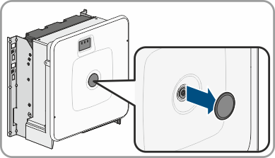
- Remove the cover from the enclosure lid.
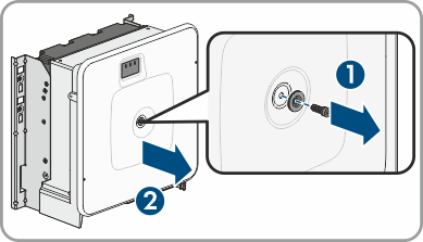
- Unscrew the screw on the enclosure lid (hex socket, AF8) and remove the enclosure lid.
- Set the cover, screw with seal, washer with seal and enclosure lid aside and store safely.
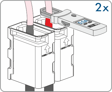
- Use a current clamp to ensure that no current is present in the DC cables. As a result, a possible residual current can be detected.
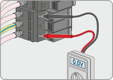
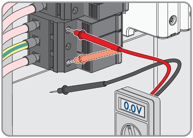
- Ensure that no voltage is present between the positive terminal and negative terminal on the DC surge protection devices using a suitable measuring device. To do so, insert the test probe (maximum diameter: 2.5 mm) into the measuring points of the DC surge protection devices.
- Ensure that no voltage is present between the positive terminal and ground as well as between the negative terminal and ground on the DC surge protection devices using a suitable measuring device. To do so, insert a test probe (maximum diameter: 2.5 mm) into the measuring points of the DC surge protection devices and hold the other one, for example, on the enclosure.
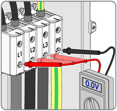
- Ensure that no voltage is present on the AC terminal block between L1 and grounding conductor, L2 and grounding conductor, and L3 and grounding conductor using a suitable measuring device. To do so, insert the test probe (maximum diameter: 2.5 mm) into the measuring points of the respective terminal blocks.
- Optional: Shut off the transformer.