Connecting CAN communication cable
 Qualified person

Communication between Inverter and Battery
- Communication between the inverter and the battery takes place via the battery communication cable via CAN bus.
Additionally required material (not included in the scope of delivery):
-
One battery communication cable for the communication between inverter and battery
Requirement for the communication cable:
-
Twisted pair conductors
-
Cable category: minimum CAT5e
-
Shielding: yes
-
Conductor cross-section: 0.25 mm² to 0.34 mm²
-
Recommended number of conductor pairs: 4
-
Maximum cable length: 10 m
-
The cable has to be insulated for 600 V.
-
UV-resistant for outdoor use. SMA Solar Technology AG recommends the cable "UC900 SS23 Cat.7 PE"
-
Comply with the requirements of the battery manufacturer.
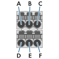
Assignment of the terminal block:
|
Terminal block |
Position |
Assignment |
|---|---|---|
|
|
A |
Not assigned |
|
B |
Enable | |
|
C |
GND and shielding | |
|
D |
CAN L | |
|
E |
CAN H | |
|
F |
Not assigned |
Procedure:
- Thread the swivel nut over the data cable of the battery.
- Route the data cable of the battery through an opening in the cable support sleeve.
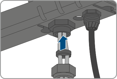
- Insert the data cable of the battery through the cable gland.
- Dismantle the data cable of the battery.
- Strip the insulation off the wires. The CAN L and CAN H must be a twisted pair.
- If necessary, trim unused insulated conductors flush with the cable sheath or fold it over the cable sheath.
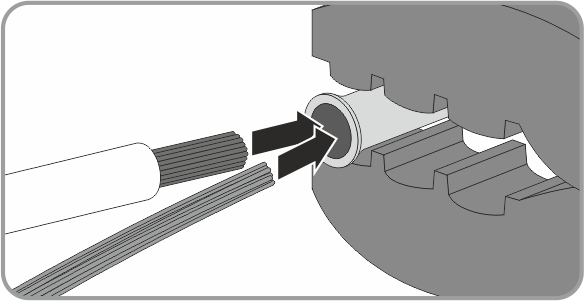
- Twist the cable shield together and insert it into a bootlace ferrule (1.5 mm² without collar) together with the GND conductor and crimp using a crimping tool.
- Connect the shielding and GND with the bootlace ferrule to the GND terminal of the plug for the battery communication connection. Observe the plug assignment.
- Connect the remaining conductors of the battery communication cable to the 6-pole terminal block. Pay attention to the assignment of the terminal block and communication connection on the battery and/or automatic transfer switch and make sure that CAN L and CAN H consist of a pair of conductors.
- Ensure that the conductors are plugged into the terminal points tightly by pulling slightly on the conductors.
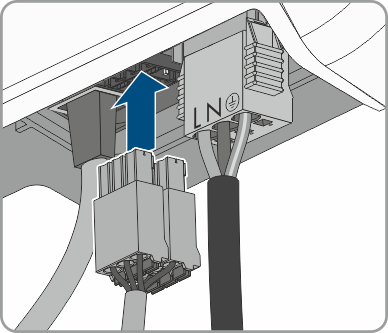
- Insert the terminal block into the jack on the right of the network jack. The terminal points must face forwards and the operating levers must face to the rear towards the mounting surface.
- Ensure that the terminal block is plugged into the jack tightly.
- Press the cable support sleeve into the cable gland.
- Screw the swivel nut hand-tight onto the cable gland for the connection of the network cable and the battery communication cable.
- Tighten the connection cap to the inverter using the three screws and a Torx screwdriver (TX20) (torque: 3.5 Nm).
- Screw the swivel nuts onto the cable glands on the connection cap.
- Connect the other end of the battery communication cable directly to the battery (see the battery manufacturer's manual).