Connecting the Network Cables
 Qualified person
 DANGER
Danger to life due to electric shock in case of overvoltages and if surge protection is missing
Overvoltages (e. g. in the event of a flash of lightning) can be further conducted into the building and to other connected devices in the same network via the network cables or other data cables if there is no surge protection. Touching live parts and cables results in death or lethal injuries due to electric shock.
- Ensure that all devices in the same network and the battery are integrated into the existing surge protection.
- When laying the network cables or other data cables outdoors, it must be ensured that a suitable surge protection device is provided at the transition point of the cable from the product or the battery outdoors to the inside of a building.

Failure-free operation of all system components due to tethered connection
- To ensure failure-free operation, SMA Solar Technology AG recommends connecting all system components with each other via Speedwire.
Additionally required material (not included in the scope of delivery):
1 network cable
Where required: Field-assembly RJ45 connector for the network cable. SMA Solar Technology AG recommends the connector "MFP8 T568 A Cat.6A" from "Telegärtner".
Network cable requirements:
The cable length and quality affect the quality of the signal. Observe the following cable requirements.
-
Cable type: 100BaseTx
-
Cable category: minimum CAT5e
-
Plug type: RJ45 of Cat5, Cat5e or higher
-
Shielding: SF/UTP, S/UTP, SF/FTP or S/FTP
-
Number of insulated conductor pairs and insulated conductor cross-section: at least 2 x 2 x 0.22 mm²
-
Maximum cable length between two nodes when using patch cables: 50 m (164 ft)
-
Maximum cable length between two nodes when using installation cables: 100 m (328 ft)
-
UV-resistant for outdoor use.
Procedure:
- When using a self-assembly network cable, assemble the RJ45 connectors and connect them to the network cable (see connector documentation).
- Unscrew the swivel nut from the cable gland for the connection of a network cable and the battery communication cable at the connection cap.
- Thread the swivel nut over the network cable.
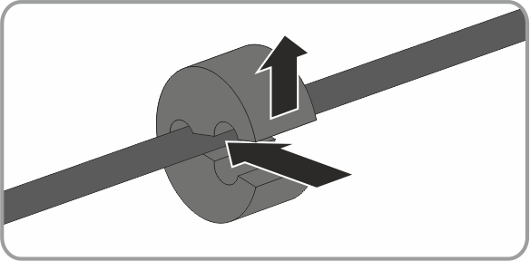
- Press the cable support sleeve out of the cable gland.
- Remove the filler plug from the cable support sleeve.
- Route the network cable through an opening in the cable support sleeve.
- Thread the network cable through the cable gland.
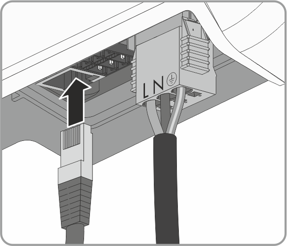
- Insert the RJ45 plug of the network cable into the network pin connector on the inverter until it snaps into place.
- Ensure that the network connector is securely in place by pulling slightly on the network cable.
- Connect the other end of the network cable to the local network (e.g. via a router). You can only connect the inverter to other nodes via star topology.
- Connecting the data cable of the battery ( > Connecting CAN communication cable).