Mounting the Inverter
 Qualified person
Additionally required mounting material (not included in the scope of delivery):
- Three screws suitable for the support surface (diameter: 10 mm at maximum)
- Three washers suitable for the screws (diameter: 30 mm at maximum)
- Where necessary, three screw anchors suitable for the support surface and the screws
- For transporting the inverter with a crane: two eye bolts suitable for the weight of the inverter (size: M10)
- To secure the inverter against theft: one padlock suitable for outdoor use
CAUTION
Risk of injury due to weight of product
Injuries may result if the product is lifted incorrectly or dropped while being transported or mounted.
- Transport and lift the inverter carefully. In doing so, keep in mind the weight of the inverter.
- Wear suitable personal protective equipment for all work on the product.
CAUTION
Risk of burns due to hot enclosure parts
Some parts of the enclosure can get hot during operation.
- Mount the inverter in such a way that it cannot be touched inadvertently during operation.
Procedure:
- Ensure that no lines are laid in the wall which could be damaged when drilling holes.
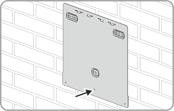
- Align the rear panel horizontally on the wall and use it to mark the position of the drill holes for attaching the rear panel. Use at least one hole on the upper right and the upper left and the hole in the middle of the rear panel.
- If the inverter is to be secured against theft, mark the drill hole for the attachment of the eye bolt.
- Set the rear panel aside and drill the marked holes.
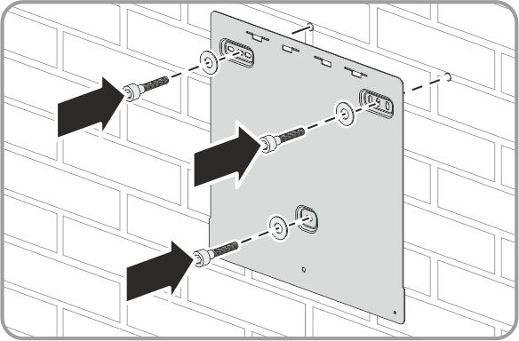
- Depending on the support surface, insert the screw anchors into the drill holes for attaching the rear panel.
- Secure the rear panel using screws and washers.
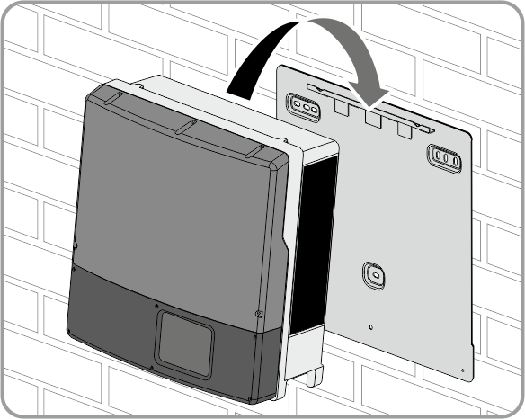
- Hook the inverter into the rear panel. The enclosure has to be flush with the rear panel on the right-hand and on the left-hand side.
- If the inverter has been transported with a crane, remove the eye bolts from the threads on the top of the inverter and reinsert the filler plugs.
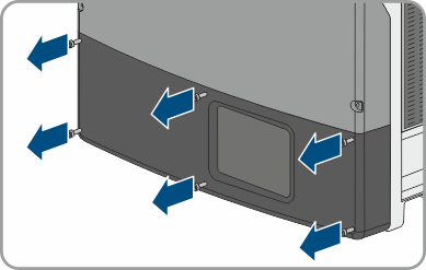
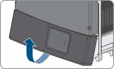
- Remove all 6 screws from the lower enclosure lid using an Allen key (AF 3).
- Flip the lower enclosure lid up and remove it.
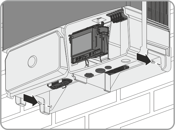
- Fasten the inverter to the rear panel. Tighten the two cylindrical screws M5x10 in the threads on the left-hand and right-hand side of the rear panel (torque: 6 Nm ± 0.3 Nm) using an Allen key (AF 4).
- Ensure that the inverter is securely in place.
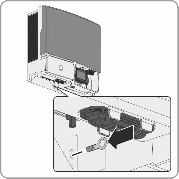
- If the inverter is to be protected against theft, attach the eye bolt and install the padlock:
Screw the M8 eye bolt into the wall through the rear panel. When tightened, the eye of the bolt must be vertical to the enclosure.
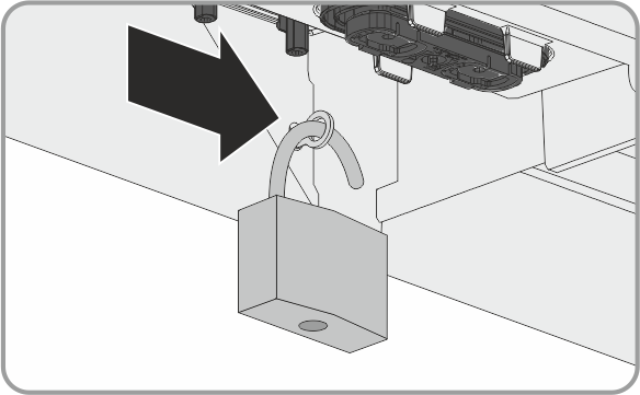
Lead the shackle of the padlock through the hole of the eye bolt.
Close the padlock.
Keep the key of the padlock in a safe place.
CAUTION
Risk of injury due to damaged cables
There may be power cables or other supply lines (e.g. gas or water) routed in the wall.