Connecting the connections to the automatic transfer switching device
Requirement:
The lid of the enclosure of the automatic transfer switching device has been opened or removed.
The installation cover of the automatic transfer switching device has been removed.
Procedure:
- Disconnect the inverter from voltage sources (see inverter manual).
- Switch off the battery (see battery manual).
- Switch off the AC fuse in the meter cabinet.
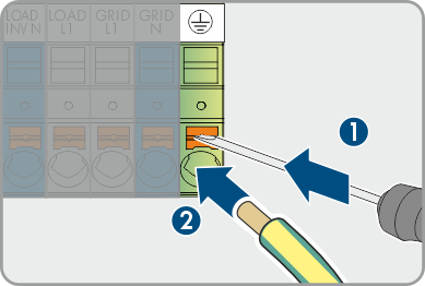
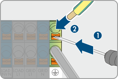
- Connect the grounding cable to the connection on the automatic transfer switching device. To do this, unlock the terminal with a suitable tool (blade width 5.5 mm).
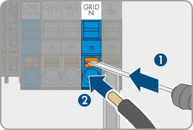
- Connect conductor N for connection to the utility grid to the GRID N connection on the automatic transfer switching device. To do this, unlock the terminal with a suitable tool (blade width 5.5 mm).
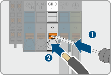
- Connect conductor L1 for connection to the utility grid to the GRID L1 connection on the automatic transfer switching device. To do this, unlock the terminal with a suitable tool (blade width 5.5 mm).
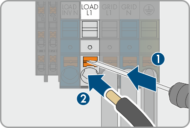
- Connect conductor L1 for the backup loads to the LOAD L1 connection on the automatic transfer switching device. To do this, unlock the terminal with a suitable tool (blade width 5.5 mm).
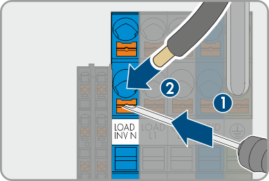
- Optional: Connect conductor N for the backup loads to the LOAD N connection on the automatic transfer switching device. To do this, unlock the terminal with a suitable tool (blade width 5.5 mm).
- Connect conductor PE for the backup loads to the LOAD PE connection on the automatic transfer switching device. To do this, unlock the terminal with a suitable tool (blade width 5.5 mm).
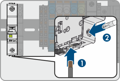
- Connect conductor L1 to the INV L1 connection on the fuse block in the automatic transfer switching device.
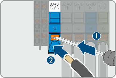
- Connect conductor N to the INV N connection on the fuse block in the automatic transfer switching device.
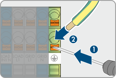
- Connect conductor PE to the INV PE connection on the fuse block in the automatic transfer switching device.
- Connect conductors L1, N and PE to the inverter (see inverter manual).
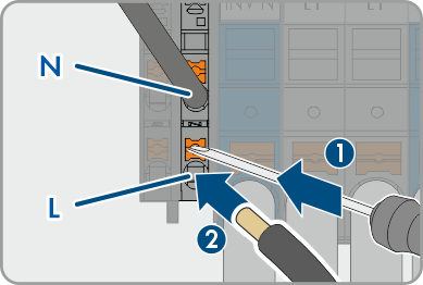
- Connect the SPS OUT AC cable to the L and N connections on the automatic transfer switching device as labeled. To do this, unlock the terminal with a suitable tool (blade width 3.5 mm).
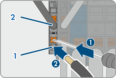
- Connect the SPS IN AC cable to the 1 and 2 connections on the automatic transfer switching device as labeled. To do this, unlock the terminal with a suitable tool (blade width 3.5 mm).
- Tug lightly to ensure that all conductors are secured in the terminals.