
Material for Automatic Transfer Switching Device of a Three-Phase Battery-Backup System with All-Pole Disconnection
The following table refers to the design of the battery-backup system with Sunny Island and summarizes the configuration of the automatic transfer switching device as suggested in the schematic diagram. You will need to procure the material for configuring your automatic transfer switching device from your distributor.

Design of the devices in the automatic transfer switching device
The indicated values for the devices are recommended SMA Solar Technology AG. The electrical devices must be designed in accordance with the locally applicable standards and directives.
Position | Material | Number of units | Design |
|---|---|---|---|
F1 | Thermal fuse for protecting the control cables and measuring cables and for protecting the multifunction relay in the Sunny Island | 3 | 1 A, cold resistance of at least 0.2 Ω, melting integral of max. 1 A²s |
F2 | Residual-current device for control and measuring cables1) | 1 | 40 A/0.03 A, 1-pole + N, type A |
F5 | Thermal fuse for protecting the control cables and for protecting the multifunction relay in the Sunny Island | 1 | 1 A, cold resistance of at least 0.2 Ω, melting integral of max. 1 A²s |
F6 | Circuit breaker for protection of the Sunny Island | 1 | 32 A, C rating, 1-pole |
F7 | Residual-current device | 1 | 40 A/0.03 A, 3-pole + N, type A |
Q2 | Contactor for grid disconnection | 1 | 400 V, 63 A bei AC-1, AC-7a, 4 no |
Auxiliary switch for feedback | 1 | 1 nc | |
Q3 | Contactor for grounding device | 1 | 400 V, 40 A at AC-1, AC-7a, 2 no 2 nc |
Auxiliary switch for Q1 locking mechanism | 1 | 1 no | |
Q4 | Contactor for grounding device | 1 | 400 V, 40 A at AC-1, AC-7a, 2 no 2 nc |
X1 | 3-conductor through terminal | 3 | 16 mm², 1-pole, 3 contact points, gray |
3-conductor through terminal | 1 | 16 mm², 1-pole, 3 contact points, blue | |
3-conductor through terminal | 1 | 16 mm², 1-pole, 3 contact points, yellow-green | |
End plate for through terminal, 3-conductor | 1 | – | |
Group marker carrier for end clamp | 1 | – | |
End clamp | 1 | Width: 10 mm | |
X2 | 3-conductor through terminal | 3 | 16 mm², 1-pole, 3 contact points, gray |
3-conductor through terminal | 1 | 16 mm², 1-pole, 3 contact points, blue | |
3-conductor through terminal | 1 | 16 mm², 1-pole, 3 contact points, yellow-green | |
End plate for through terminal, 3-conductor | 1 | – | |
Group marker carrier for end clamp | 1 | – | |
End clamp | 1 | Width: 10 mm | |
X3 | 3-conductor through terminal | 3 | 10 mm², 1-pole, 3 contact points, gray |
3-conductor through terminal | 3 | 10 mm², 1-pole, 3 contact points, blue | |
3-conductor through terminal | 3 | 10 mm², 1-pole, 3 contact points, yellow-green | |
End plate for through terminal, 3-conductor | 1 | – | |
Group marker carrier for end clamp | 1 | – | |
End clamp | 1 | Width: 10 mm | |
X4 | 3-conductor through terminal | 5 | 2.5 mm², 1-pole, 3 contact points, gray |
3-conductor through terminal | 3 | 2.5 mm², 1-pole, 3 contact points, blue | |
End plate for through terminal, 3-conductor | 1 | – | |
Group marker carrier for end clamp | 1 | – | |
End clamp | 1 | Width: 10 mm | |
X5 | 3-conductor through terminal | 4 | 1.5 mm², 1-pole, 3 contact points, gray |
3-conductor through terminal (L) | 1 | 6 mm², 1-pole, 3 contact points, gray | |
3-conductor through terminal (N) | 1 | 6 mm², 1-pole, 3 contact points, blue | |
End plate for through terminal, 3-conductor | 2 | – | |
Group marker carrier for end clamp | 1 | – | |
End clamp | 1 | Width: 10 mm | |
Z1 | Sunny Home Manager 2.0 | 1 | – |
1) Required in TT grid configuration only
Configuration suggestion
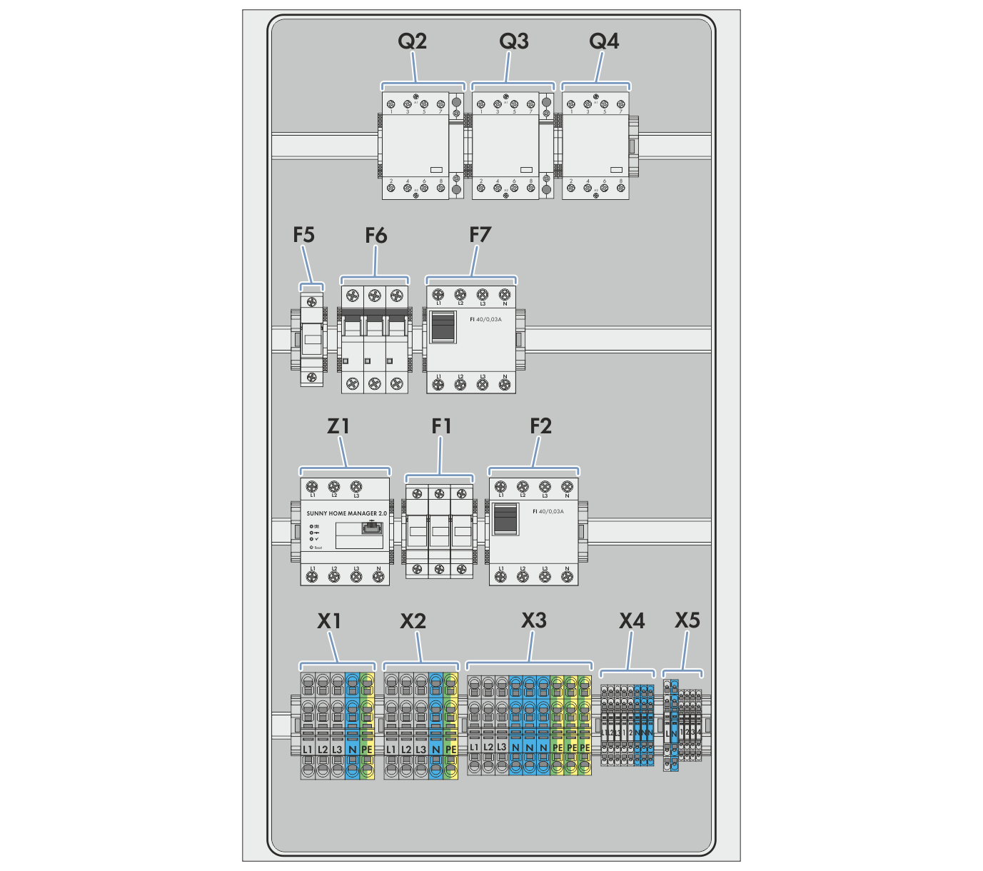
Configuration suggestion for three-phase automatic transfer switching device with all-pole disconnection