
Power Control in Accordance with the Summation Current Principle
If, with a three-phase grid connection, an SMA Energy System Home or a single-phase hybrid or battery inverter is installed, power control in accordance with the summation current principle also applies. The summation current principle must also be applied when the three-phase Sunny Tripower Smart Energy feeds in symmetrically since single-phase electrical appliances result in an asymmetrical power distribution on the line conductors.

Requirement: cumulative meter values
With a three-phase grid connection and a PV system with a single-phase inverter, only those loads that are connected to the same line conductor are physically supplied with self-generated solar power. The excess current, which these loads do not require, is fed into the utility grid. At the same time, it can happen that electric current is required on one of the other two line conductors, which then has to be purchased from the utility grid. To minimize the complexity of billing, instead of using a phase-specific approach, a balance sheet approach is used for the energy flows. So-called cumulative meters offset the current fed into one line conductor against the other two line conductors. Phase powers taken from the utility grid are provided with a negative sign and phase powers fed into the utility grid are provided with a positive sign and then added up to form a total power. This ensures that electronic meters behave just as conventional Ferraris meters. In this way, all loads in the house can be supplied with self-generated solar power and only the difference between current generation and current consumption is fed into the utility grid or purchased. A cumulative meter value, however, does not permit any conclusion to be drawn about the power flows and directions of each individual line conductor.
The Sunny Home Manager 2.0 and the SMA Energy Meter supply balanced measured values. Installation must be downstream of the billing-relevant meter in the same power path.

In an SMA Energy System Home, the battery or hybrid inverter is in charge of the intermediate storage over all three line conductors of the grid connection. For power control in accordance with the summation current principle, the storage system uses the cumulative values of the SMA Energy Meter or of the Sunny Home Manager 2.0 for grid feed-in and grid-supplied power. Depending on the grid operator's local requirements, the measurement interval of the SMA Energy Meter or the Sunny Home Manager 2.0 must be adjusted from 1000 ms to 200 ms.
Implementation of the summation current principle is explained below with the example of the SMA Energy System Home and three different situations.
Situation 1:
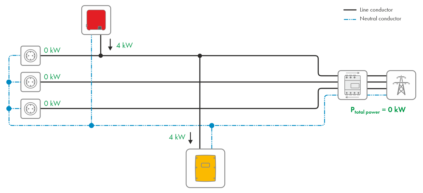
The battery inverter charges the battery.
It is early morning. At sunrise, the PV system begins to feed in and after a while reaches electric power of 4 kW. The loads are still switched off.

First, the PV system feeds the total PV power into the utility grid via phase 1. The battery inverter recognizes the grid feed-in, switches on immediately and uses the PV power of 4 kW to charge the battery.

Thus, no more cumulative power is fed into the utility grid.
Situation 2:
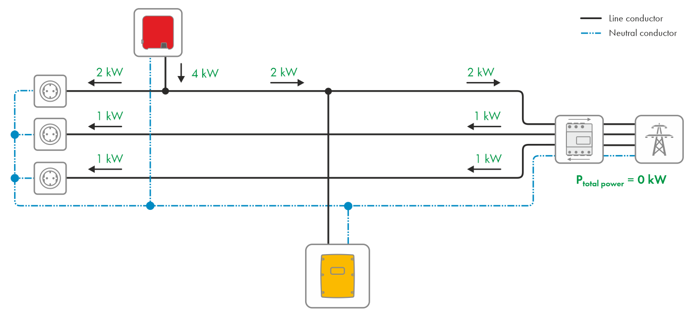
The loads are using the total PV power.
It is around noon. The battery is fully charged. The PV system provides 4 kW. The load on phase 1 uses the power generated by the PV system directly which, therefore, now only feeds 2 kW into the utility grid. The loads on line conductors 2 and 3 draw their power of 1 kw each from the utility grid.
The total power at the bidirectional meter for grid feed-in and purchased electricity is shown as follows:

From a cumulative perspective, there is no grid feed-in and no purchase of electricity taking place. The battery inverter does not need to intervene and leaves the state of charge of the battery unchanged.
Situation 2a:
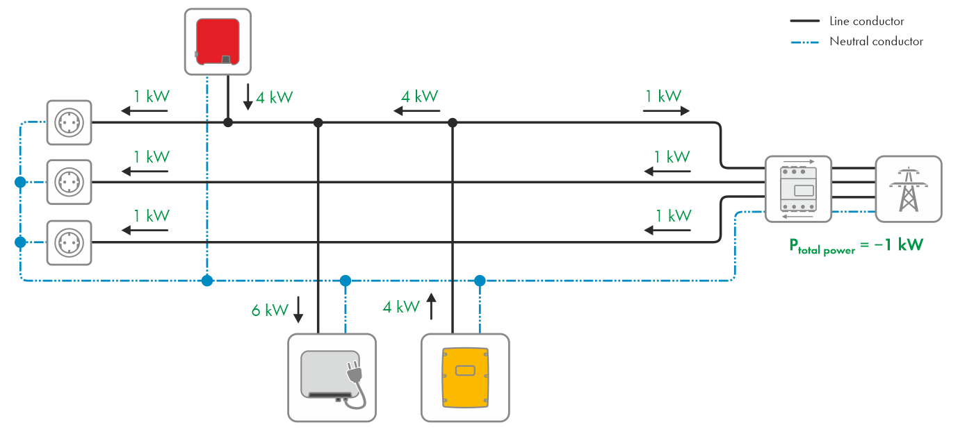
The SMA EV Charger uses the single-phase PV generation for faster charging of the electric vehicle (boost function).
It is afternoon. The battery is fully charged. The PV system provides 4 kW. The loads on line conductors L1, L2 and L3 draw 1 kW of electric power each. The charging station (SMA EV Charger) has an additional power requirement of 6 kW on line conductor L1. Thanks to the boost function of the SMA EV Charger, the power requirement of the charging station can be at least partially covered by the direct use of the electrical output of the PV system, while at the same time complying with the maximum unbalanced load limit required by the standard at the point of interconnection. The total power at the bidirectional meter for grid feed-in and purchased electricity is shown as follows:

The utility grid is now the sole energy source for the loads and supplies them with 5 kW. The battery inverter detects the purchased electricity and consequently uses the energy from intermediate storage to supply the loads. The total power at the bidirectional meter for grid feed-in and purchased electricity is shown as follows:

The energy stored intermediately by the battery inverter in the battery is insufficient to completely supply the loads. There is a low grid-supplied power of 1 kW.
Situation 3:
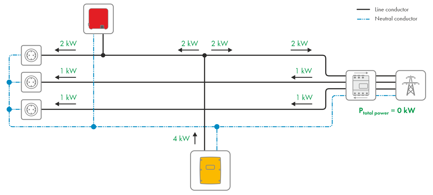
The battery inverter supplies the loads with energy from intermediate storage.
It is now evening. The PV system is not feeding in. The loads are switched on and are drawing 2 kW of electric power on phase 1, 1 kW on phase 2, and 1 kW on phase 3.
The total power at the bidirectional meter for grid feed-in and purchased electricity is shown as follows:

The utility grid is now the sole energy source for the loads and supplies them with 4 kW. The battery inverter detects the purchased electricity and consequently uses the energy from intermediate storage to supply the loads.
The total power at the bidirectional meter for grid feed-in and purchased electricity is shown as follows:
The energy stored intermediately by the battery inverter in the battery is sufficient to supply the loads. No more electricity is purchased from the grid.