Mounting the Product and Preparing the Connection
 Qualified person
 DANGER
Danger to life due to electric shock when live cables are touched
High voltages are present on the AC and DC cables. Touching live cables results in death or lethal injuries due to electric shock.
- Do not touch non-insulated parts or cables.
- Disconnect the AC circuit breaker and secure it against reconnection.
- Disconnect the PV array from the inverter via an external DC load-break switch (e.g. via a PV junction including a load-break switch). Switch off and secure the DC load-break switch against reconnection.
- Ensure that all cables to be connected are de-energized.
- Wear suitable personal protective equipment for all work on the product.
CAUTION
Risk of injury due to weight of product
Injuries may result if the product is lifted incorrectly or dropped while being transported or mounted.
- Transport and lift the product carefully. Take the weight of the product into account.
- Wear suitable personal protective equipment for all work on the product.
- Transport the product using the carrying handles or hoist. Take the weight of the product into account.
- Use all carrying handles provided during transport with carrying handles.
- Do not use the carrying handles as attachment points for hoist equipment (e.g. straps, ropes, chains). Insert eye bolts into threads provided on top of the product to attach the hoist system.
Procedure:
- Mark the position for the mounting brackets.
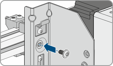
- Hook each mounting bracket onto the mounting rail and insert the screw (M8x105).
- Fasten all four screws of each mounting bracket hand-tight (TX40).
- Ensure the correct position of the mounting brackets by hooking in the mounting template. If the position is incorrect, move the mounting brackets to the correct position.
- Tighten all four screws of each mounting bracket (TX40, torque: 12 Nm ± 2 Nm).
- Clip the mounting template into the mounting brackets.
- Align the cables by means of the mounting template and shorten if necessary. Take the product depth of 400 mm into account.
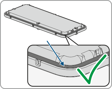
- Check on the connection plate whether the seal is present and undamaged.
- Thread the swivel nuts of the cable glands over the cables.
- Attach the cable glands to the connecting plate.
- Lead the cables through the cable glands in the connecting plate and align the connecting plate by means of the mounting template.
- Remove the mounting template.
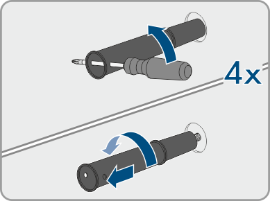
- Screw the transport handles as far as they will go into the taps on the right- and left-hand side until they lie flush with the enclosure. When doing so, ensure that the transport handles are screwed into the taps so that they are perfectly straight. If the transport handles are not screwed in straight, this can make it more difficult or even impossible to unscrew them later on and can damage the taps to the extent that transport handles can no longer be screwed into them.
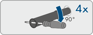
- Insert a screwdriver into the holes in the transport handle and turn the screwdriver through 90°. This ensures that the transport handles are securely tightened.
- If the inverter is to be hooked into the mounting brackets by means of a hoist, screw the eye bolts into the threads on the top of the inverter and attach the hoist to them. The hoist must be suitable to take the weight of the inverter.
- Unscrew all screws of the enclosure lid (TX25) and remove it.
- Set the screws and the enclosure lid aside and store safely.
- Hook the product into the mounting brackets. To do this, guide the product over the cables and the connecting plate so that the cables protrude through the opening into the product and the connecting plate sits under the opening. The bracket must protrude through the upper opening.
- Align the cables according to the corresponding terminals and shorten the cables if necessary.
- Secure the product with one screw each on the right and left on the mounting bracket (M8x16, TX40, 12 Nm ± 2 Nm).
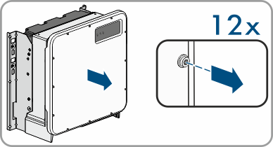
- Remove all four transport handles from the threaded holes. If necessary, insert a screwdriver into the holes on the transport handle and use the screwdriver to remove the transport handle.
- Fasten the connecting plate to the enclosure using three screws (M8x70, TX40, torque: 8 Nm ± 0.5 Nm).