Connecting the Network Cables
 Qualified person
 DANGER
Danger to life due to electric shock in case of overvoltages and if surge protection is missing
Overvoltages (e. g. in the event of a flash of lightning) can be further conducted into the building and to other connected devices in the same network via the network cables or other data cables if there is no surge protection. Touching live parts and cables results in death or lethal injuries due to electric shock.
- Ensure that all devices in the same network are integrated in the existing overvoltage protection.
- When laying the network cable outdoors, ensure that there is suitable surge protection at the network cable transition from the product outdoors to the network inside the building.
- The Ethernet interface of the product is classified as "TNV-1" and offers protection against overvoltages of up to 1.5 kV.
Additionally required material (not included in the scope of delivery):
Network cables
Where required: Field-assembly RJ45 connector.
Network cable requirements:
The cable length and quality affect the quality of the signal. Observe the following cable requirements:
-
Cable type: 100BaseTx
-
Cable category: minimum CAT5e
-
Plug type: RJ45 of Cat5, Cat5e or higher
-
Shielding: SF/UTP, S/UTP, SF/FTP or S/FTP
-
Number of insulated conductor pairs and insulated conductor cross-section: at least 2 x 2 x 0.22 mm²
-
Maximum cable length between two nodes when using patch cables: 50 m
-
Maximum cable length between two nodes when using installation cables: 100 m
-
UV-resistant for outdoor use.
Laying the cables:

Interior view of the product with laying plan for network cables
Procedure:
- Disconnect the inverter from all voltage sources ( > Disconnecting the Inverter from Voltage Sources).
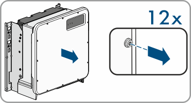
- If the enclosure lid is closed, remove the screws of the enclosure lid (TX 25) and remove the enclosure lid.
- When using a self-assembly network cable, assemble the RJ45 connectors and connect them to the network cable (see connector documentation).
- Thread a swivel nut over each network cable.
- For each cable attach a cable gland to the connection plate.
- Lead each cable through a cable gland in the connection plate up to the network jacks. Lay each cable according to the installation plan and attach to the brackets.
- Put the RJ45 plug of the cable into one of the network sockets of the communication assembly.
- Ensure that the RJ45 plug is securely in place by pulling slightly on the cable.
- Firmly tighten the swivel nut on each cable gland.
- If the inverter is installed outdoors, install overvoltage protection for all components in the network.
- Either connect the other end of the network cable directly to the local network (e.g. via a router) or connect all present inverters in the system to each other in line topology and connect the first or last inverter in the line to the local network.
DANGER
Danger to life due to electric shock