Connecting the Inverter to the Utility Grid
 Qualified person
Requirements:
- The connection requirements of the grid operator must be met.
- The grid voltage must be in the permissible range. The exact operating range of the inverter is specified in the operating parameters.
Procedure:
- Disconnect the circuit breaker and secure it against reconnection.
- If an additional DC load-break switch is available, switch off the DC load-break switch and secure against reconnection.
- If the ESS is installed and plugged in, remove the ESS.
- If the lower enclosure lid is mounted, loosen all screws of the lower enclosure lid using an Allen key (AF 3) and remove the enclosure lid.
- Loosen the screw on the display and flip the display up to have more space to make the connection.
- The display clicks into place.
- Unscrew the swivel nut from the cable gland.
- If the outer diameter of the cable is between 15 mm and 21 mm, remove the inner sealing ring from the cable gland.
- Move the swivel nut of the cable gland over the AC cable and then route the AC cable through the cable gland into the inverter.
- Dismantle the AC cable.
- Shorten L and N by 5 mm each.
- Strip the insulation of L, N and the grounding conductor by 18 mm.
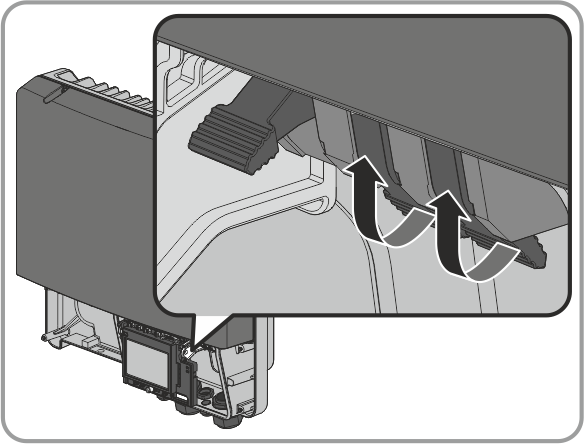
- Push the locking levers of the connecting terminal plate for the AC cable right up to the stop.
- Connect the grounding conductor, N and L to the connecting terminal plate for the AC cable in accordance with the labeling.
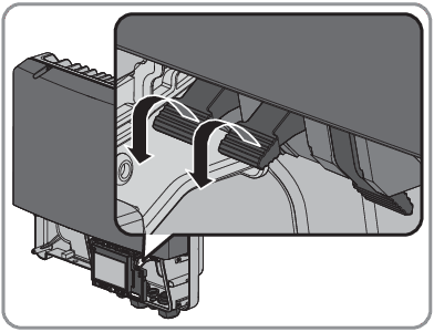
- Press the locking levers of the connecting terminal plate for the AC cable down with your thumb only.
- Do not grip the entire connecting terminal plate for the AC cable.
- Do not place your fingers under the locking levers.
- Make sure that all conductors are securely in place.
- Screw the swivel nut onto the cable gland.
- If the display is flipped up, flip it down and tighten the screw.
CAUTION
Danger of crushing fingers when locking levers snap shut
The locking levers close by snapping down fast and hard.