
Interior View
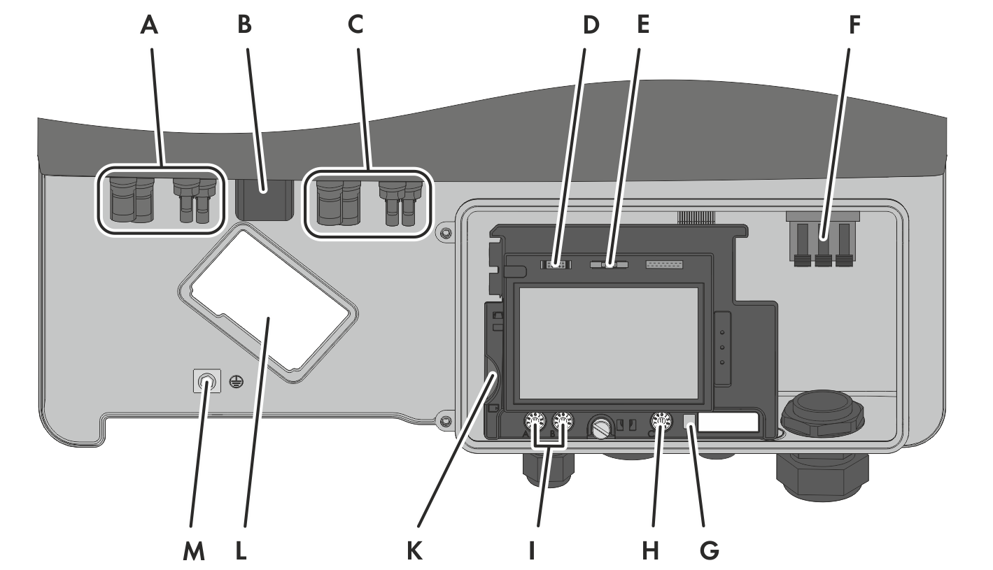
Connection areas in the interior of the inverter
|
Position |
Designation |
|---|---|
|
A |
2 positive and 2 negative DC connectors, input A |
|
B |
Pin connector for the ESS* |
|
C |
2 positive and 2 negative DC connectors, input B |
|
D |
Pin connector for connecting the multifunction relay, the SMA Power Control Module or the fan retrofit kit* |
|
E |
Pin connector for connecting the Speedwire/Webconnect interface or the RS485 interface* |
|
F |
Connecting terminal plate for connecting the AC cable |
|
G |
Switch for temporarily changing the display language to English (for service purposes) |
|
H |
Rotary switch C for configuring the NetID |
|
I |
Rotary switch A and B for setting the country data set and the display language |
|
K |
Slot for SD memory card |
|
L |
Mounting location for the fan retrofit kit* |
|
M |
Grounding terminal for additional grounding of the inverter |
* Optional