
Interfaces and Functions
The inverter can be equipped or retrofitted with the following interfaces and functions:
User interface for monitoring and configuration
The product is equipped as standard with an integrated webserver, which provides a user interface for configuring and monitoring the product. The product user interface can be called up via the web browser if there is an existing connection to an end device (e.g. computer, tablet PC or smartphone).
Smart Inverter Screen
The Smart Inverter Screen enables you to view the status display and to display the nominal energy throughput and state of charge of the battery on the user interface login page. You therefore have an overview of the most important inverter and battery data without having to log into the user interface.
The Smart Inverter Screen is deactivated by default. The Smart Inverter Screen can be activated via the user interface once the inverter has been commissioned.
SMA Speedwire
The product is equipped with SMA Speedwire as standard. SMA Speedwire is a type of communication based on the Ethernet standard. SMA Speedwire is designed for a data transfer rate of 100 Mbps and enables optimum communication between Speedwire devices within systems.
Class 1 wiring methods are to be used for field wiring connection to the terminals of the communication interface.
SMA Webconnect
The inverter is equipped with a Webconnect function as standard. The Webconnect function enables direct data transmission between the inverters and Internet portals Sunny Portal and Sunny Places without any additional communication device and for a maximum of 1 inverters per visualized system. In PV systems with more than 1 inverters, there is the option of establishing data transmission between the inverters and Sunny Portal via the data logger (e.g., SMA Data Manager) or distributing the inverters over several systems. If there is an existing WLAN or Ethernet connection, you can directly access your visualized system via the web browser on your end device.
WLAN
The product is equipped with a WLAN interface as standard. The inverter is delivered with the WLAN interface activated as standard. If you do not want to use WLAN, you can deactivate the WLAN interface.
In addition, the product has a WPS function. The WPS function is for automatically connecting the product to a network (e.g. via router) and establish a direct connection between the product and an end device.
Modbus
The product is equipped with two Modbus interfaces.
One interface can be controlled via Ethernet and the other interface via RS485. The Modbus interface via Ethernet is designed for industrial use – via SCADA systems, for example – and deactivated as standard. The Modbus interface via Ethernet must be configured via the user interface of the inverter (if necessary). The Modbus interface via RS485 is used for data exchanges with an energy meter. The Modbus interface via RS485 must be configured via the user interface of the inverter and set on the energy meter accordingly.
The Modbus interface via Ethernet has the following tasks:
-
Remote query of measured values
-
Remote setting of operating parameters
-
Setpoint specifications for system control
-
Controlling the battery
Grid Management Services
The inverter is a grid support multi-mode inverter.
The inverter was tested in accordance with the UL 1741 SA (2016-09-07) to be compliant with the source requirements documents of the states available at the time. For connecting the inverter to the utility grid, no additional grid monitoring equipment is necessary. A description of the tested functions and instructions on the activation and setting of functions can be found in the technical information "Grid Support Utility Interactive Inverters" at www.SMA-Solar.com.
Secure power supply operation
In case of a grid failure, the secure power supply operation supplies the loads with energy from the battery. You can connect a standard outlet (120 V) and a standard switch to the inverter. You can connect a load with a maximum of 16 A and 120 V to the emergency power outlet. The load is supplied with energy from the battery during grid failure. The switch is used to enable and disable secure power supply operation.
The secure power supply operation is not automatically enabled in the event of a grid failure, neither is it automatically disabled once the utility grid is available again. If the utility grid fails, the load supply must be enabled manually by activating the switch. The inverter automatically regulates the energy supply of the outlet after activating the switch. When the utility grid is available again and the load can be supplied by this again, the secure power supply operation must be disabled manually by switching the switch off.
During active secure power supply operation, the inverter is disconnected from the building's main electrical system and does not therefore feed into the utility grid. During secure power supply operation, the load can only be supplied with energy as long as there is stored energy available in the battery. If there is insufficient energy available from the battery, the secure power supply operation remains active, even if the utility grid is available again. Switching over to supplying the load from the utility grid is not carried out automatically.

Secure power supply operation in Flexible Storage Systems with backup power supply not possible
If the inverter is used in a battery-backup system and connected with an automatic transfer switch, the secure power supply operation is not available.
Do not connect any loads that require an uninterrupted energy supply
The secure power supply operation and the battery-backup operation may not be used for loads that require a uninterrupted energy supply. The energy that is available during the secure power supply operation or battery-backup operation depends on the battery capacity available and the state of charge of the battery (SOC).
- Do not connect loads if they are dependent on an uninterrupted energy supply for reliable operation.
Battery-backup function
The inverter is equipped with a battery-backup function. The battery-backup function is disabled by default and must be enabled via the user interface. The battery-backup function can only be enabled if the inverter is operated in a battery-backup system with an automatic transfer switching device. If the system is retrofitted with an automatic transfer switching device, the battery configuration must be reset and carried out once again. Then the battery-backup system must be configured. The configuration is carried out via the installation assistant on the user interface of the battery inverter.
The battery-backup function ensures that the inverter forms a battery-backup grid that uses energy from the battery and the PV system to supply the household grid in the event of a utility grid failure. When the battery-backup operation is activated, the automatic transfer switch disconnects the PV system and the household grid from the utility grid in the event of a grid failure, and connects these to the battery-backup grid. After a short switch-over time, the battery-backup grid and loads connected can be supplied by the battery and supplemented with energy from the PV system. The charging of the battery is ensured by the existing PV system during battery-backup operation. The charging process of the battery (initiated by the PV system) can be deactivated via a certain parameter during battery-backup operation. As soon as the utility grid is available again, the battery-backup operation is disabled automatically and the loads are supplied with energy from the utility grid. If the automatic battery-backup operation is not set, the battery-backup operation must be manually enabled in the event of a grid failure, and must also be disabled again once the utility grid is available (information in terms of switching operations of the automatic transfer switch and procedures during grid failure and grid reconnection see planning guidelines "SMA FLEXIBLE STORAGE SYSTEM with Battery-Backup Function").
When the utility grid is down and the battery fully discharged, there is, in the beginning, not enough power available to create a stable battery-backup grid. In this case, the battery must be charged by the PV system. The battery inverter is able to create a stable battery-backup grid only when enough power is available in the battery. To use battery charging power from the PV system, the battery inverter has to create a stand-alone grid. For this purpose, the battery inverter requires energy from the battery reserve. If enough PV power is available, the PV inverters start automatically and the battery is charged with energy from the PV system. The battery is charged with energy until the battery inverter is able to provide a battery-backup grid. By setting parameters, it is possible to define up to which state of charge the battery is charged and discharged. If not enough PV energy is available to start the PV inverters, the stand-alone grid breaks down. Two hours later, the battery inverter tries to start the PV inverter again to charge the battery with energy from the PV system. If the battery inverter still fails to create a stand-alone grid after several attempts due to insufficient PV energy, the battery inverter and battery switch to sleep mode. In this case, a manual black start is required to switch the battery inverter and battery from sleep mode back to operation.
Secure power supply operation in Flexible Storage Systems with backup power supply not possible
If the inverter is used in a battery-backup system and connected with an automatic transfer switch, the secure power supply operation is not available.
Do not connect any loads that require an uninterrupted energy supply
The secure power supply operation and the battery-backup operation may not be used for loads that require a uninterrupted energy supply. The energy that is available during the secure power supply operation or battery-backup operation depends on the battery capacity available and the state of charge of the battery (SOC).
- Do not connect loads if they are dependent on an uninterrupted energy supply for reliable operation.
Black start function
The inverter has a black start function and an auxiliary battery that provides energy for the black start. In battery-backup systems, you have the possibility to install a standard switch for black starting the inverter and battery. The black-start switch is used to start the battery-backup operation manually in the event of grid failure if the battery and inverter are in sleep mode and, therefore, are unable to provide energy. When the black-start switch is switched on manually, the energy from the auxiliary battery is made available in order to automatically switch the battery and therefore also the inverter from sleep mode to operation in order that the inverter can make energy available from the battery. You can stop the battery-backup operation by switching it off manually. To enable the black-start function, at least one battery must be connected to input A.
Multi-battery device
The product is equipped with the multi-battery function as standard from firmware version 1.50.10.R. The multi-battery function enables to charge and discharge several batteries of the same or different type. If the system is extended by one or several batteries or one battery is replaced, the battery configuration must be reset and carried out again. The configuration is carried out via the installation assistant on the user interface of the battery inverter. An overview of batteries approved by SMA Solar Technology AG and their possible combinations is available at www.SMA-Solar.com.
SMA Smart Connected
SMA Smart Connected is the free monitoring of the inverter via the SMA Sunny Portal. Thanks to SMA Smart Connected, the PV system operator and qualified person will be informed automatically and proactively about inverter events that occur.
SMA Smart Connected is activated during registration in Sunny Portal. In order to use SMA Smart Connected, it is necessary that the inverter is permanently connected to Sunny Portal and the data of the PV system operator and qualified person is stored in Sunny Portal and up-to-date.
Time-of-Use
With the "Time-of-Use" function, you can adjust the charging behavior of the battery to your electricity tariff. Energy bills are thus reduced and electricity at lower cost can be used. You can determine in which time range the battery with a specified charging power is operated. At specific times, this is mostly useful when the battery's state of charge has to take on a certain value or the tariff situation makes the charging more attractive, regardless of the power at the grid-connection point. The charging parameters set in the power profile are only limited by the state of charge (SOC). At times when the "Time-of-Use" function is not enabled, the battery is charged correspondent to the increased self-consumption for the entire system. The "Time-of-Use" function is disabled by default and must be enabled by creating power profiles.
Peak load shaving
With the "Peak Load Shaving" function, you can optimize the behavior of the battery inverter with respect to the power exchange at the grid-connection point. This is mostly useful when a higher supply of energy would lead to a higher electricity cost. With the "Peak Load Shaving" function, certain grid-exchange power outputs to which the battery inverter is adjusted depending on its power and battery capacity available can be set. Power peaks can thus be avoided.
You can configure times and setpoints for the power drawn at the grid-connection point. When the loads require additional energy, the battery is discharged and the maximum value is kept constant at the grid-connection point. This is based on the prerequisite that the battery is sufficiently charged. At times when the "Peak Load Shaving" function is not activated, the battery is charged or discharged correspondent to the increased self-consumption for the entire system. The "Peak Load Shaving" function is deactivated by default and must be activated by creating power profiles.
Frequency Shift Power Control
If PV inverters are connected on the AC side during battery-backup operation, the battery inverter must be able to limit their output power. This limitation becomes necessary when, for example, the battery inverter's battery is fully charged and the power available from the PV system exceeds the power requirement of the connected loads.
To prevent excess energy from overcharging the battery, the battery inverter automatically detects the problem and changes the frequency at the AC output. This frequency adjustment is analyzed by the PV inverter. As soon as the power frequency of the battery-backup grid increases beyond the value specified in f Start Delta, the PV inverter limits its output power accordingly.
The frequency shift power control is enabled by default. No additional settings must be carried out. It must be ensured that the connected PV inverters limit their power at the AC output via the battery inverter due to changes in frequency. The frequency-dependent active power limitation P(f) must be set in the PV inverter.
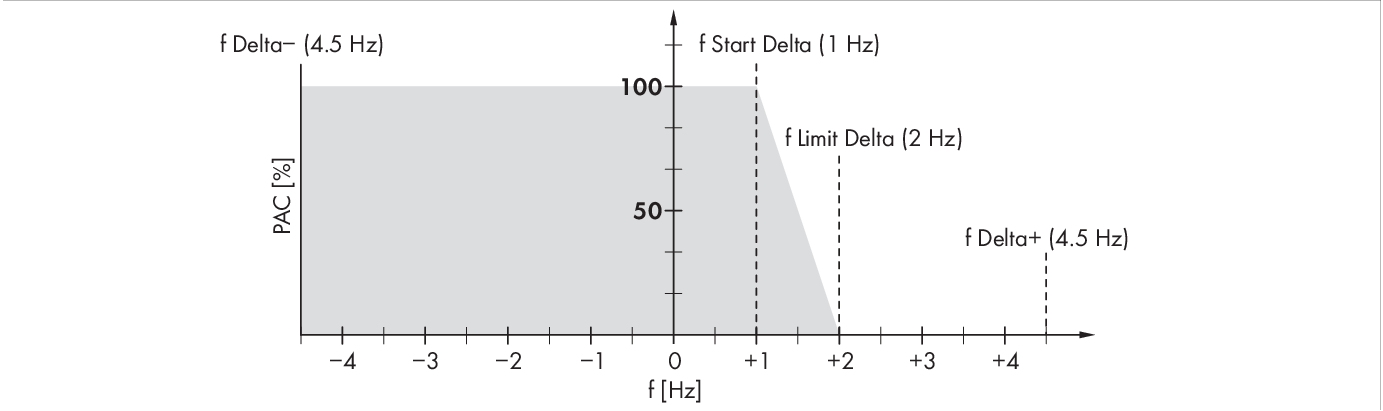
Impact of the frequency shift power control on the power output of a PV inverter
|
Designation |
Explanation |
|---|---|
|
f |
Base frequency of the stand-alone grid |
|
f Delta- to f Delta+ |
Maximum range in relation to the base frequency in which the PV inverter is active. |
|
f Start Delta |
Frequency increase in relation to the base frequency, at which point the power regulation via frequency begins. |
|
f Limit Delta |
Frequency increase in relation to the base frequency, at which point the power regulation via frequency ends. The power of the PV inverter at this point is 0 W. |