
Connecting Signal Source to Digital Input
Digital signals for the active power supply can be transmitted to the jack X3. A ripple control receiver or a remote terminal unit can be used as a digital signal source, for example.
-
Digital signal source with up to 4 potential-free contacts
-
Connection cable
Requirements:
The signal source must be technically suitable for connection to the digital inputs ( > Technical Data).
-
The connection cable must be prepared for connection to the multipole terminal block ( > Preparing the Connection Cable).
Overview:

Pin assignment
|
Pin |
Pin assignment |
Explanation |
|---|---|---|
|
1 |
DI1 |
Digital input |
|
2 |
DI2 |
Digital input |
|
3 |
DI3 |
Digital input |
|
4 |
DI4 |
Digital input |
|
5 |
DI5 |
Fast stop* |
|
6 |
24 V |
Voltage supply output |
* With the fast-stop function, depending on the set inverter operating mode, inverters can be disconnected from the utility grid or enter into standby operation. For further information on SMA products with fast-stop function see manual of the SMA products.
Circuitry overview:
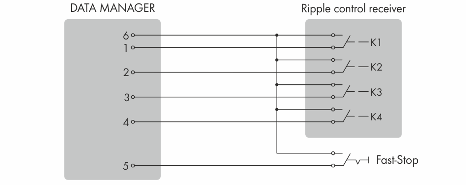
Connection of a Ripple Control Receiver
- Connect the connection cable to the digital signal source (see the manual from manufacturer).
- Connect the connection cable to the supplied six-pole plug. For this, unlock the required terminal positions using a suitable tool and plug the conductors into these terminal positions.
- Connect the six-pole plug to terminal X3. Observe the pin assignment.
- Note the terminal assignment.