Connecting the cables to BU-STPH-4P63K
Requirement:
- The meter cabinet is open.
Procedure:
- Disconnect the inverter from all voltage sources (see inverter manual).
- Switch off the battery (see battery manual).
- Switch off the grid-side AC fuse in the meter cabinet.
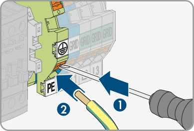
- Connect conductor PE for connection to the utility grid to the PE terminal on the automatic transfer switching device. To do this, unlock the terminal with a suitable tool (blade width 5.5 mm).
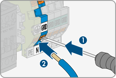
- Connect conductor N for connection to the utility grid to the N terminal on the automatic transfer switching device. To do this, unlock the terminal with a suitable tool (blade width 5.5 mm).
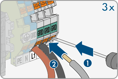
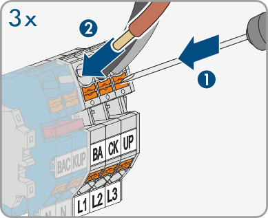
- Connect conductors L1, L2 and L3 for the connections to the utility grid to the GRID L1, GRID L2 and GRID L3 terminals on the automatic transfer switching device. To do this, unlock the terminals with a suitable tool (blade width 5.5 mm).
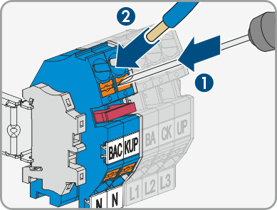
- Connect conductor N for the connection of the backup loads to the N terminal on the automatic transfer switching device. To do this, unlock the terminal with a suitable tool (blade width 5.5 mm).
- Connect conductors L1, L2 and L3 for the backup loads to the Backup L1, Backup L2 and Backup L3 terminals on the automatic transfer switching device. To do this, unlock the terminals with a suitable tool (blade width 5.5 mm).
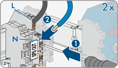
- Connect the SPS OUT AC cable to the L and N terminals on the automatic transfer switching device as labeled. To do this, unlock the terminal with a suitable tool (blade width 3.5 mm).
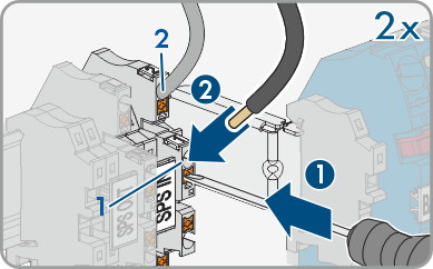
- Connect the SPS IN AC cable to the 1 and 2 terminals on the automatic transfer switching device as labeled. To do this, unlock the terminal with a suitable tool (blade width 3.5 mm).
- Ensure that all conductors are securely in place.