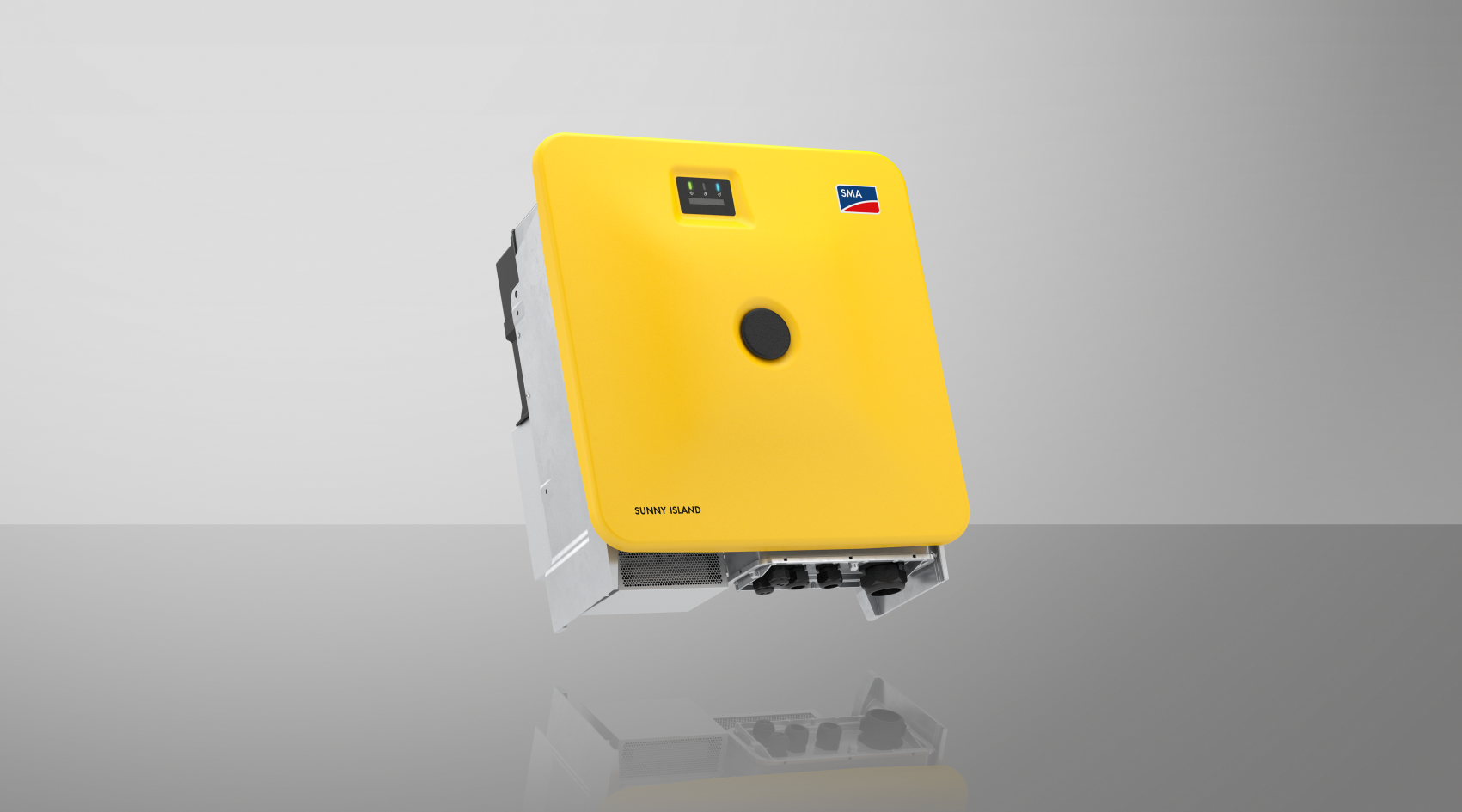
Operating manual
SUNNY ISLAND X 30 / 50
SI30-20 / SI50-20
- Information on this Document
- Safety
- Scope of delivery
- Additionally Required Materials and Equipment
- Product overview
- Device function
- System overview
- Sunny Island X as System Manager - System with Utility Grid
- SMA Data Manager M as System Manager - System with Utility Grid
- SMA Hybrid Controller as System Manager - System with a Generator
- SMA Hybrid Controller as System Manager - System with Utility Grid
- SMA Hybrid Controller as System Manager - System with Utility Grid and Generator
- SMA Hybrid Controller as System Manager - System with Multiple Generators
- Sunny Island X as System Manager - System with Utility Grid
- Product Description
- Symbols on the Inverter
- Interfaces and Functions
- User Interface
- SMA Speedwire
- Wi-Fi connection to SMA 360° app and SMA Energy app
- Device Key (DEV KEY)
- Modbus
- Grid Management Services
- Integrated Plant Control
- Increased self-consumption
- Peak load shaving
- Multiuse
- Stand-alone grid function
- Module slot
- SMA I/O modules
- Grid and PV system protection in accordance with VDE-AR-N 4105
- Ripple control receiver
- SMA Smart Connected
- User Interface
- Battery Use by the Inverter
- LED Signals
- Device function
- Mounting and Preparing the Connection
- Electrical Connection
- Requirements for the electrical connection
- Residual-current monitoring unit (RCMU)
- Overvoltage category
- Load-break switch and cable protection
- Equipotential Bonding
- AC cable requirements
- Network cable requirements
- Battery data cable requirements
- Pin assignment of RJ45 plug connector for battery communication via CAN bus
- Laying plan for network and battery data cables
- Ripple control receiver and external I/O system
- DC cable requirements
- Residual-current monitoring unit (RCMU)
- Overview of the Connection Area
- DC connection overview
- Electrical connection procedure
- Connecting the AC Cable
- Connecting the Network Cables
- Connecting the battery communication cable for Modbus
- Connecting the battery communication cable for CAN
- Connecting the DC Cables
- Requirements for the electrical connection
- Commissioning
- Operation
- Establishing a Connection to the User Interface
- Design of the User Interface
- Access rights to the user interface
- Energy management
- Configuring the battery
- Carry out a manual firmware update
- Backup file
- Resetting the product to default setting
- Delete user accounts
- Digital input
- Starting the inverter
- Stopping the inverter
- Disconnecting the Inverter from Voltage Sources
- Cleaning
- Troubleshooting
- Event messages
- Event 301
- Event 401
- Event 404
- Event 501
- Event 502
- Event 503
- Event 601
- Event 701
- Event 1302
- Event 3302
- Event 3303
- Event 3501
- Event 3523
- Event 3601
- Event 3701
- Event 3901
- Event 3902
- Event 6001-6499
- Event 6501
- Event 6502
- Event 6509
- Event 6511
- Event 6512
- Event 6602
- Event 6603
- Event 6802
- Event 6804
- Event 6805
- Event 7001
- Event 7702
- Event 7703
- Event 7727
- Event 7728
- Event 7801
- Event 8003
- Event 8104
- Event 8708
- Event 8709
- Event 8710
- Event 9002
- Event 9003
- Event 9007
- Event 9101
- Event 9102
- Event 9107
- Event 9206
- Event 9303
- Event 9307
- Event 9308
- Event 9311
- Event 9312
- Event 9313
- Event 9314
- Event 9315
- Event 9316
- Event 9350
- Event 9351
- Event 9352
- Event 9353
- Event 9369
- Event 9392
- Event 9393
- Event 9394
- Event 9395
- Event 10816
- Event 10817
- Event 10818
- Event 10819
- Event 10820
- Event 301
- Replacing the Surge Arrester
- Cleaning the fans of the inverter
- Checking the fans of the inverter
- Event messages
- Decommissioning
- Disposal
- Replace the inverter with a replacement device
- Technical Data
- Accessories
- EU Declaration of Conformity
- UK Declaration of Conformity
- Contact

